How to draw a German Eisernkreuz
Martin Héctor Afflitto Echagüe found this description in an
old german book in an Argentine Aeronautical library. It describes the
dimensions of a german Eisern Kreuz.
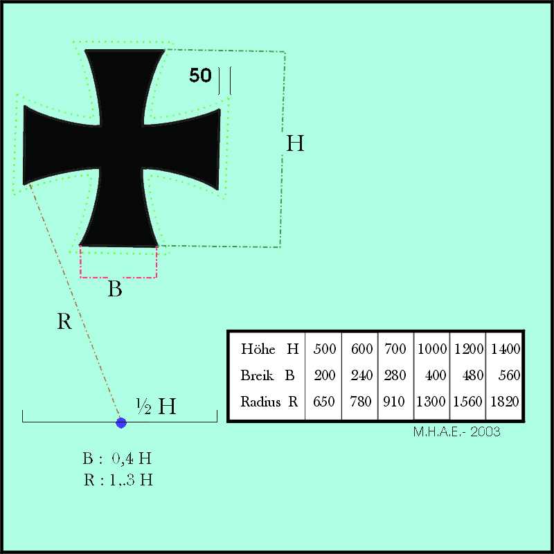
Diagram (reproduced)
Martin reproduced the diagram by hand.
Accompanying Text
The text in German is as follows:
Hoheitsabzeichen
An den Enden der Oberseite der oberen tragflächen an der Unterseite der
unteren Flächen, beiderseits in der Mitte des Rumpfes und auf beiden Seiten
des Seitensteuers erhalten die Flugzeuge in größtmöglichster
Abmessung die
deuchen Hoheitsabzeichen in Form des "Eisernen Kreuzes ", in schwarzer
Farbe. Das Kreuz erhält eine etwa 5 cm breite weiße Umrandung.
Für die Abmessungen bezw .
Formen des Kreuzes sind die in Fig. 114 angegebenen Abmessungen zu wählen.
Der flugzeugrumpf erhält außerdem beiderseits neben dem Kreuz die
Typenbezeichnung und Flugzeugnummer.
Translation (bei Hans Trauner)
National Markings
The German national markings are applied to the very ends of the uppersides
of upper wings, on the underside of the
lower wings, on both sides of the middle of the fuselage and on both sides
of the rudder. The markings are in
maximum possible dimension in form of the 'Iron Cross', in black colour.
The cross has a white border of approx. 5 cm width.
For the measurements and form,
the measurements of Fig. 114 are used.
In addition, the type designation and Aircraft Serial number (Flugzeugnummer)
are applied to both sides of the aircraft.
Hans notes:
This Figure 114 is taken from an order of July 25th 1916. Interestingly in
this order the ratio of radius to height is given as 1:1.4, despite the
given measurements. This 1.4 ratio included the white border!
Alternate instructions
Tom Solinski offers:
I found the same information (dimensions) in newer form in an issue of
Flying Scale Models two years ago. Great numbers but constructing it is
a draftsman's nightmare. For those of you who want to practice drawing
these "Iron Crosses" may I suggest the following process using a
straight edge, ruler and compass?
- Draw a vertical line the desired height of the cross. This forms the
vertical "H" in the sketch.
- Draw a horizontal line the same length as the first line that bisects
the first line. The horizontal "H" in the sketch.
- At the end point of each of these lines draw two perpendicular lines
that are one-fourth the length of the original vertical lines one
running in each direction away from the base line. These form the
vertical and horizontal "B"s in the sketch. 1/4H + 1/4H = 1/2H=B)
- Label the endpoints of the "B"s as (working clockwise): top left,
top right; right top, right bottom; bottom right, bottom left; and left
bottom, left top.
- Draw and extension of the original lines from steps a & b above out
at least one "H" unit long.
- Take your compass and set it to 1.3 x "H" wide, this is the dimension
"R" in the sketch.
- Set the point of the compass on the "top right" endpoint from step d
above and strike an arc on the extension line to the right of the cross.
- Move the compass to the intersection just drawn on the extension
line, and strike an arc from the "top right" to the "bottom right" end
points in step d above. Now you have the first curve established.
- Repeat steps g & h for the other three legs of the cross.
- Erase anything that doesn't look like a cross.
That was easy wasn't it?
Reference
Title : Das Flugzeug Und sein Aufbau,
Bibliothek für Luftschiaffahrt und Flugtecchnik,
Band 17
Author : Knut Anacker ( Ingenieur und Flugzeugführer)
Publisher :
Richard Carl Schmitdt & Co.,
Berlin W 62,
Januar 1918