
This article originally appeared in the September 2000 issue of Internet Modeler.
 "The
Showbirds" - Ben Casey's 'Zig-Zag'
"The
Showbirds" - Ben Casey's 'Zig-Zag'
DML 1/48 SPAD XIII

by Ernest Thomas
Introduction
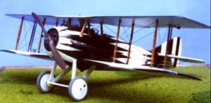
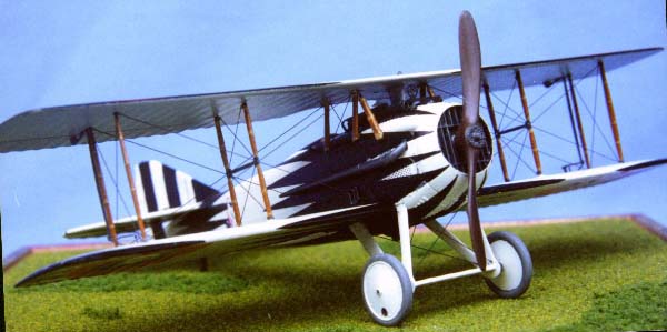
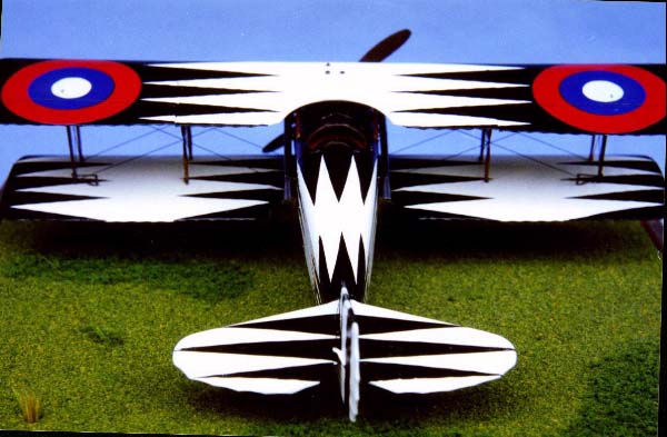
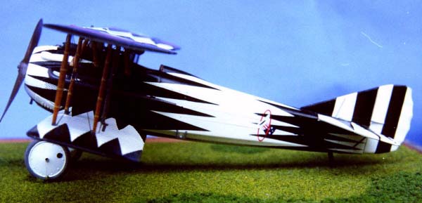
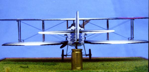
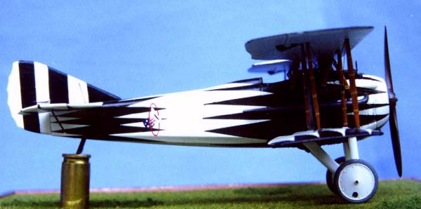
Being rather fond of colorful aircraft, I tend to build a lot of WWI German models. So when Bob Pearson emailed me a page of very colorful Spad profiles, I jumped at the chance to build a non-German bird in such crazy plumage. As the first of what I hope will be a series of models, I chose Lt. Ben 'Casey' Jones' mount, sporting a striking black and white 'Splinter' scheme. For the kit, the obvious choice was the excellent DML offering. It's the best 1/48 Spad XIII available. And having built this kit twice before, I knew where to expect trouble and was prepared to deal with it. There's not a lot of trouble, but it's there.
The Cockpit
 The
cockpit is first rate, straight out of the box. Just about everything
that's in the real plane is included in this kit. The only things missing
are bracing, control, and instrument wires, which I'm glad DML didn't
try to mold in – I would have had to remove it and ruin the excellent
detail.. It's also missing a piece of plumbing for from where a fuel tank
would go behind the seat. There's no fuel tank either but you can't see
back there anyway.
The
cockpit is first rate, straight out of the box. Just about everything
that's in the real plane is included in this kit. The only things missing
are bracing, control, and instrument wires, which I'm glad DML didn't
try to mold in – I would have had to remove it and ruin the excellent
detail.. It's also missing a piece of plumbing for from where a fuel tank
would go behind the seat. There's no fuel tank either but you can't see
back there anyway.
First step after cleaning all the parts is to start painting the sidewalls of the cockpit. A Spad cockpit is made up of wood structure with linen covering, some ply, and sheet metal panels, as well as a few steel tube members. For the structure, I use a medium reddish brown. Humbrol 62, in this instance. Plywood panels were Humbrol Wood, with metal panels painted a dark olive. For clear doped linens, I use whatever cream color I have handy, Humbrol 103 being a favorite. The variety of colors makes things more interesting to look at.
 After
everything is painted, I then add the bracing wires on the sidwalls, made
from .006 brass wire dipped in "Blacken-it", which is a product that blackens
metal. It can be found in the model RR section of the hobby shop. All
the side wall detail parts are attached next. These include the throttle,
compass, mageneto, and wires that run from under the instrument shelf,
forward to the engine. I then built the floor panel/seat/controls assembly
as directed, doing nothing more that adding two bits of brass rod to make
up for the missing fuel lines and wires running from the rudder bar towards
the back of the plane.. Also, you must cut the tip off the top of the
fuel fill pipe (part B20) or it will cause trouble when trying to fit
B27 and A8 together.
After
everything is painted, I then add the bracing wires on the sidwalls, made
from .006 brass wire dipped in "Blacken-it", which is a product that blackens
metal. It can be found in the model RR section of the hobby shop. All
the side wall detail parts are attached next. These include the throttle,
compass, mageneto, and wires that run from under the instrument shelf,
forward to the engine. I then built the floor panel/seat/controls assembly
as directed, doing nothing more that adding two bits of brass rod to make
up for the missing fuel lines and wires running from the rudder bar towards
the back of the plane.. Also, you must cut the tip off the top of the
fuel fill pipe (part B20) or it will cause trouble when trying to fit
B27 and A8 together.
 Once
all the sub-assemblies are built and painted, it's time to close the fuselage,
which goes off without a hitch. It doesn't even need much putty if you're
careful about the alignment of the two halves. The instrument shelf (part
B27) is one of the little problems. It's too thick and causes problems
fitting the top decking for the guns and cockpit opening (part A8). But
you only need to bevel the side edges from the underside get a good fit.
After that, you just assemble as directed and paint it.
Once
all the sub-assemblies are built and painted, it's time to close the fuselage,
which goes off without a hitch. It doesn't even need much putty if you're
careful about the alignment of the two halves. The instrument shelf (part
B27) is one of the little problems. It's too thick and causes problems
fitting the top decking for the guns and cockpit opening (part A8). But
you only need to bevel the side edges from the underside get a good fit.
After that, you just assemble as directed and paint it.
The shelf, and the panel(B28) are made of wood on the real bird. I painted them three different shades of brown and red/brown, with brass switches and grey bolts on the raised bit on B27. The photo etched instruments were painted black, then lightly sanded to remove the black paint from the raised bezels while leaving the recessed faces black.
 When
the glue and paint are dry, proceed with the assembly according to the
instructions. There's no real big surprises or traps from here on out,
but there are a few things worth knowing about.. The headrest cushion
is too small so I made one from sheet styrene. Also, on the PE spent shellcase
chutes, don't forget to remove one of the end tabs before you try and
fold it into the box shape. I completely missed that little detail on
the instructions the first time I built this model and ended up scratch
building them.
When
the glue and paint are dry, proceed with the assembly according to the
instructions. There's no real big surprises or traps from here on out,
but there are a few things worth knowing about.. The headrest cushion
is too small so I made one from sheet styrene. Also, on the PE spent shellcase
chutes, don't forget to remove one of the end tabs before you try and
fold it into the box shape. I completely missed that little detail on
the instructions the first time I built this model and ended up scratch
building them.
The tail plane assembly goes without a hitch, but the lower wing, chin piece(part A9) and top decking(part A8) all need a bit of filler around the seams. I used a needle to apply small amounts of CA directly into the seams, being careful to avoid putting too much and the risk of sanding away the detail when trying to remove any excess.
 A
few words on the photo-etch parts are in order. The exhaust pipe brackets(parts
MA21) fit in their slots like a glove, so put these on before any painting
is done on the outside fuselage. Same for the side grills(parts MA3/MA4),
chin grill?(part MA30) and the rudder control horns(parts MA20) I also
find all those little rigging attach brackets are too overscaled and didn't
use them. Same for the PE cabane rigging (parts MA17/MA18) . They're just
so much thicker than the .006 wire I use for the rest of the rigging.
And finally, the 'H' struts. I have no idea why they were done in PE.
It's clear from the quality of all the other plastic parts that DML could
have made better ones in plastic. But being PE, they're just too flat
when viewed from head on. The portions on either side of the cross members
will have to be thickened with white glue or CA to match the outboard
mainplane struts. This is also true for the foremost Cabane members (parts
MA5). I also don't know why DML put those little tabs sticking out the
tips of the 'H' struts, but the slots that they fit in on the wings are
too shallow and make the tabs stick up, and none of my references show
anything like that on the real aircraft. So they should be removed. Then
the oversized slots have to be filled around the struts. It's all a big,
unnecessary headache that could have been avoided with plastic 'H' struts.
A
few words on the photo-etch parts are in order. The exhaust pipe brackets(parts
MA21) fit in their slots like a glove, so put these on before any painting
is done on the outside fuselage. Same for the side grills(parts MA3/MA4),
chin grill?(part MA30) and the rudder control horns(parts MA20) I also
find all those little rigging attach brackets are too overscaled and didn't
use them. Same for the PE cabane rigging (parts MA17/MA18) . They're just
so much thicker than the .006 wire I use for the rest of the rigging.
And finally, the 'H' struts. I have no idea why they were done in PE.
It's clear from the quality of all the other plastic parts that DML could
have made better ones in plastic. But being PE, they're just too flat
when viewed from head on. The portions on either side of the cross members
will have to be thickened with white glue or CA to match the outboard
mainplane struts. This is also true for the foremost Cabane members (parts
MA5). I also don't know why DML put those little tabs sticking out the
tips of the 'H' struts, but the slots that they fit in on the wings are
too shallow and make the tabs stick up, and none of my references show
anything like that on the real aircraft. So they should be removed. Then
the oversized slots have to be filled around the struts. It's all a big,
unnecessary headache that could have been avoided with plastic 'H' struts.
 And
since we're now talking about struts, I must say that the cabane struts
are perhaps the most well designed struts I've ever seen on a model biplane.
Same for the undercarriage struts. The positive, solid attach points make
it simple to get a strong and straight assembly. And that makes attaching
the top wing a snap. The joint where the undercarriage struts attach to
the spreader bar(part A13) need a bit of filling and sanding, but it's
a sturdy assembly which makes it easy to fix.
And
since we're now talking about struts, I must say that the cabane struts
are perhaps the most well designed struts I've ever seen on a model biplane.
Same for the undercarriage struts. The positive, solid attach points make
it simple to get a strong and straight assembly. And that makes attaching
the top wing a snap. The joint where the undercarriage struts attach to
the spreader bar(part A13) need a bit of filling and sanding, but it's
a sturdy assembly which makes it easy to fix.
At this point, every thing just sorta falls together. The top wing rest securely on the cabanes and the mainplane struts can be popped into place after the wing is secured to the cabanes. When attaching the aileron linkage, it's best to attach parts MA11/MA12 to the top wing and then fitting parts MA31 in place. And that's about all I can say on building this model.
Painting
 This
model was painted in my typical manner for a biplane. The model was assembled
almost up to the point of attaching the top wing, less wheels, prop, skid,
guns, windscreen, pipes, etc... I then mask off the cockpit opening and
sprayed the entire model white. All the black splinters were cut from
black decal film. It really was pretty simple. After the entire model
was splintered, I applied a clear coat and proceeded with final assembly.
This
model was painted in my typical manner for a biplane. The model was assembled
almost up to the point of attaching the top wing, less wheels, prop, skid,
guns, windscreen, pipes, etc... I then mask off the cockpit opening and
sprayed the entire model white. All the black splinters were cut from
black decal film. It really was pretty simple. After the entire model
was splintered, I applied a clear coat and proceeded with final assembly.
I would like to thank Bob Pearson, Dale Beamish, Lance Kriege, Steve Perry and Mike DiCianna for their invaluable assistance on this project.