
This article originally appeared in the May 1999 issue of Internet Modeler.
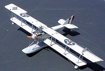
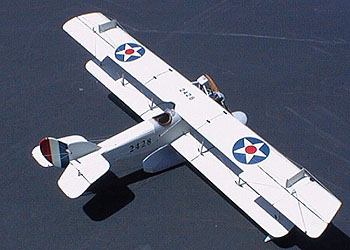
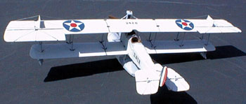
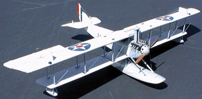
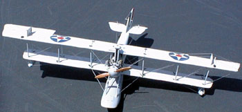
Seagoing Jenny - The Curtiss N9-H
Converting the Lindberg JN-4 into the N9-H
By Steve Perry
 When I first saw
Carl Parks article on making a Curtiss N-9H out of several Lindberg Jenny
kits in the July 1995 FSM, I fell in love with the plane and began collecting
Jenny kits. When I had the prescribed three, I began planning the project.
The first thing I noticed about making N-9's out of Lindberg Jennys is
that you only need two kits. All that Mr. Parks used out of the third
kit were the lower wings to make the large barn door upper wing ailerons.
These are just as well made from card and you can save the $8 for that
third Jenny and spend it on a Lindberg SE5 to get the Hispano-Suiza motor
included in that kit and needed on the N-9H.
When I first saw
Carl Parks article on making a Curtiss N-9H out of several Lindberg Jenny
kits in the July 1995 FSM, I fell in love with the plane and began collecting
Jenny kits. When I had the prescribed three, I began planning the project.
The first thing I noticed about making N-9's out of Lindberg Jennys is
that you only need two kits. All that Mr. Parks used out of the third
kit were the lower wings to make the large barn door upper wing ailerons.
These are just as well made from card and you can save the $8 for that
third Jenny and spend it on a Lindberg SE5 to get the Hispano-Suiza motor
included in that kit and needed on the N-9H.
The next thing you need to do is to obtain some drawings of the Curtiss N-9H. The ones provided in the article are OK, but you will need more detail. The source I found is the Emil Buhler Naval Aviation Library. The good people there sent me drawings showing cockpit details, rigging information and engine installations all for a very modest copying fee.
Mr. Parks went to great lengths to make a jig for assembling the top wing. I found that a good razor saw. a bit of plastic wrap to glue on, a flat surface and a straight edge were the bare essentials. Do pay close attention to Mr Parks description of exactly where to make the cuts in the wing pieces though. Be sure you make a right tip and a left tip for each of the wings, in other words: "Do as I say, not as I did" and you'll have less work to do.
 I sanded off all
rib detail from both sides of both wings. Here is where I made my big
mistake. I added rib tape detail before locating all the strut positions.
Do not do this, you will not like yourself very much if you do. After
filling the original strut holes and slots with putty or CA, carefully
locate and mark the new strut positions. This is best done after the bottom
wings are joined to the fuselage. Only after you have marked the strut
locations should you attempt to add decal material for the rib tapes.
It is far better to match the tapes to the measured strut locations, than
it is to match the struts to eyeballed rib tape locations. Looks better
in the end too - believe me.
I sanded off all
rib detail from both sides of both wings. Here is where I made my big
mistake. I added rib tape detail before locating all the strut positions.
Do not do this, you will not like yourself very much if you do. After
filling the original strut holes and slots with putty or CA, carefully
locate and mark the new strut positions. This is best done after the bottom
wings are joined to the fuselage. Only after you have marked the strut
locations should you attempt to add decal material for the rib tapes.
It is far better to match the tapes to the measured strut locations, than
it is to match the struts to eyeballed rib tape locations. Looks better
in the end too - believe me.
RIB TAPES:
One of the things I did to this model that isn't covered in the FSM article are the rib tapes. This is a major feature on an aircraft with as much wing as a Curtiss N-9H and an effective means of representing this detail is needed. My method of rib taping a solid color 1:48 scale wing is just what is needed here and a description follows:
1. I sand off all or very nearly all of the rib detail on the plastic kit part. I also thin the trailing edges and add any needed corrections to the shape.
2. At least one coat of primer to show up imperfections (Scan the part at 150 dpi resolution to see EVERY imperfection). Sand and prime until the piece is satisfactorily smooth.
3. CAREFULLY mark rib stations, strut positions and rigging attach points/holes.
4. On a clean piece of glass, use double sided scotch tape to hold a piece of decal material (of a color which contrasts with your primer coat) flat on the surface. With a steel rule and a new #11 blade, slice strips of decal material the correct width for your scale (not quite 3/32 in 1:48 and a bit more than 3/64 in 1:72). Cut the strips into lengths about 1/4" longer than the chord of your wing. By slicing through the decal film but not through the backing paper, you can get several strips together. Cut this into chord lengths plus 1/4" and you can soak off many tapes at once.
5. Apply the strips of decal material to the marked rib stations. Use plenty of Solvaset to get them to settle well.
6. Paint the color coat(s)
7. Use gloss coat or Future to prep for decals and then a final semi gloss to taste.
FUSELAGE:
 The fuselage builds
up just fine with Mr. Parks' notes. Do use his technique for filling in
the nose with CA before sanding it to the new shape. It uses enough CA
to be expensive, but CA is the best substance there is for filling in
on the inside of where you intend to sand down through the original plastic
to create a new outline. It feathers perfectly and sands clear as glass.
I use this technique all the time now.
The fuselage builds
up just fine with Mr. Parks' notes. Do use his technique for filling in
the nose with CA before sanding it to the new shape. It uses enough CA
to be expensive, but CA is the best substance there is for filling in
on the inside of where you intend to sand down through the original plastic
to create a new outline. It feathers perfectly and sands clear as glass.
I use this technique all the time now.
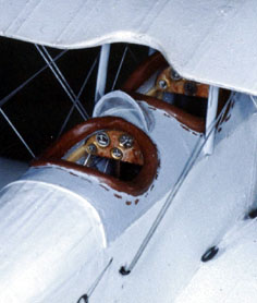
Another note on the fuselage. The N-9H had a yoke and wheel cockpit controls instead of the Jenny's joystick. This needs to be made before the fuselage goes together. Drawings from The Emil Buhler Naval Aviation Library provide this detail.
The N-9H had the Jenny's long wings extended another 10 ft in order to generate the lift needed to pull that float free from the water. There is the specter of drooping wings hanging over this whole project. The best way to prevent this is to spar the bottom wings securely. I used a piece of music wire exactly thick enough to just slip through the slot in the fuselage formerly intended for the lower wing tabs. Fortunately the floorboard hides this pass through member. I left 1.5" on either side of the fuselage. The wire spar fit into a trough I carved in the bottom of the lower wing panels. This was CA'ed and sanded smooth. I couldn't have been more pleased with the result. The bottom wing was as stiff as could be and supported the top wing with no droop.
I used the kit struts separated into individual struts. I began with the mainplane struts in the first bay (of 3) outboard of the fuselage. With these glued, I added the cabane struts trying for the best alignment. The outer two bays followed taking up misalignment as I went. With CA and a few judicious drops of kicker applied with a needle, the upper wing went on surprisingly well. Rigging a 3 bay biplane is not hard, just 2/3 more time consuming than a single bay biplane. I used double wires where the drawings indicated and Grandt line turnbuckles painted black (as were other exposed metal fittings) to represent Japaning (laquering), added a real nice touch.
The fin and rudder are shown to be made from the stab of the second Jenny kit. Save yourself some sanding and filling and just make it out of card. Be sure to add decal material taping as shown in the drawings before painting and decaling this structure. The effect is a realistic touch.
DETAILING THE HISPANO-SUIZA ENGINE
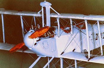 The only other major
job on this project is the detailing of a Hisso engine. The N-9H appeared
to use the ungeared version of the Hisso. Mr. Parks covers this in his
article by saying he scratch-built one. I used the Hisso engine out of
the Lindberg SE5 kit. This makes up into a nice replica with a few details
as described below.
The only other major
job on this project is the detailing of a Hisso engine. The N-9H appeared
to use the ungeared version of the Hisso. Mr. Parks covers this in his
article by saying he scratch-built one. I used the Hisso engine out of
the Lindberg SE5 kit. This makes up into a nice replica with a few details
as described below.
1. Clean up both sides of the crankcase. Remove the blob that attempts to impersonate a carb and part of the intake manifold. Decide whether you are modeling the geared or ungeared version. If necessary remove and relocate the housing from which the prop shaft exits. Glue both crankcase halves together and deal with the seams.
2. On each cylinder bank, remove the molded on mound of plastic purporting to be a portion of the intake manifold. Dress the scar. Leave the molded on exhaust flanges located on the opposite side of the bank. Using reference photos and drawings, locate the positions of the spark plugs. Stretch a piece of sprue to the diameter you want the plugs to be and drill holes just barely larger in diameter through the cylinder bank at the plug locations. Keep the drill bit at right angles in all axis so the holes come out exactly opposite the marked locations. Insert a length of sprue completely through the cylinder bank leaving plenty to trim off later on each end. Allow a tiny drop of CA to wick down along the sprue from the base of the hole into the bank.
3. Using a piece of stretched sprue, Attach it to the front end of the cylinder bank up near the top, (about 1/16" down). Now wrap each end back down each side of the bank and attach at the same height at the rear of the bank. This is the flange between the rocker cover and the head. Run a very fine bead of CA down the length of this "flange" to seal it to the rocker cover.
 4. Paint the crankcase
whatever color you determine is appropriate for the service and application
of the engine you are modeling. Paint the cylinder banks black. Carefully
dress the mating surfaces of the cylinder banks and the crankcase. Dry
fit to check for proper angles from front and side views. When happy with
the fit, glue the cylinder banks to the crankcase. This allows the little
downward projecting piece on the back of the crankcase to be used as a
handle thus protecting the details from damage during the rest of the
work.
4. Paint the crankcase
whatever color you determine is appropriate for the service and application
of the engine you are modeling. Paint the cylinder banks black. Carefully
dress the mating surfaces of the cylinder banks and the crankcase. Dry
fit to check for proper angles from front and side views. When happy with
the fit, glue the cylinder banks to the crankcase. This allows the little
downward projecting piece on the back of the crankcase to be used as a
handle thus protecting the details from damage during the rest of the
work.
5. Make two magnetos. A rectangular piece of thick card with the corners rounded and a disc sliced from rod or sprue sort of faired in together with CA will fairly well mimic the drawings and photos. Join with bits of sprue, paint and mount on the rear of the engine as per drawings and photoss. NOW is the time to check the fit of the engine and the model. Adjust both as needed. Remember, what can't be seen, won't be looked at.
6. Make four sets of spark plug wires. These can be stretched sprue, wire or thread. Paint the plugs white and the "wires" whatever color seems best, the photos show them lighter than the black cylinder banks. Fashion the clips holding the wires together out of tape, Bare Metal Foil, Acrylic gel or paint. The plug wire sets can be fashioned, then attached or the individual wires can be attached to the plugs and then gathered into the arrangement shown on the references. Adjust the dose of detail to suit the severely of your case of AMS. Attach the top and bottom sets of plug wires to each magneto.
7. Make the intake manifold from two pieces of rod heated and bent at the ends. Hold the rod in some needle nose pliers, covering exactly the straight length with the jaws of the pliers. Heat and bend the protruding ends. You have to carve and clean up the bent ends. Make the joining piece out of thick card sanded to an ovalish cross section. Make the carb body out of a piece of hollow rod sliced off and a couple of pieces of thick card laminated and whittled to shape. Fair in the join with CA. Attach to the bottom of the intake manifold. Check for fit and adjust. Paint and attach to the engine.
 8. Make straight
pipes by drilling out bits of rod the same diameter as the molded on exhaust
flanges. Use a bit only big enough for the tip of an Xacto blade. By carefully
rotating the point of the blade in the hole, the rod can be hollowed out
until the walls are nearly scale thickness. Use some kind of jig to cut
them all the same length. A piece of tape exactly the right distance from
the edge of a piece of paper works well. Hold the drilled out end flush
against the tape and cut off exactly on the edge of the paper. Attach
the pipes. The Carb throat and the drilled/scraped out ends of the pipes
need to be painted black before painting the outside.
8. Make straight
pipes by drilling out bits of rod the same diameter as the molded on exhaust
flanges. Use a bit only big enough for the tip of an Xacto blade. By carefully
rotating the point of the blade in the hole, the rod can be hollowed out
until the walls are nearly scale thickness. Use some kind of jig to cut
them all the same length. A piece of tape exactly the right distance from
the edge of a piece of paper works well. Hold the drilled out end flush
against the tape and cut off exactly on the edge of the paper. Attach
the pipes. The Carb throat and the drilled/scraped out ends of the pipes
need to be painted black before painting the outside.
9. There is some plumbing at the rear and under the engine as well as some connecting it to whatever radiator arrangement the model you are doing uses. If it shows, add it out of rod or sprue uisng the same bending technique as on the intake manifold. Using stretched sprue painted silver, attach a piece to the crankcase directly on the front edge of each cylinder bank and run it up to almost the apex of the rocker cover, bend it at right angles and trim. Attach the top end to the rocker cover. Any throttle and choke linkages can be made from sprue, wire or rod and attached after the engine is installed in the model. Various sizes of Grandt Line bolt heads can be added for detail if desired.
10. Paint anything still needing it and give the whole thing a coat of semi gloss to your taste.
I found that I had to remove the part of the engine where the prop shaft attaches in order to get the engine to fit. I glued the piece in question to the inside of the scratch-built cowl ring before inserting the engine and it lined right up when the engine dropped in. Be careful of the details during this fiddly operation.
THE FLOAT
 The float seemed
at first a most daunting project as I have never been too good at carving
and sanding. I took a 1/8" sheet of basswood and cut several rectangular
pieces large enough to cover the float outline as viewed from the top.
I glued enough of these together to make a block the height of the float
in side view using white glue. Once dry, I traced the planform and side
elevation views onto the laminated block. Careful carving and sanding
yielded a nearly perfect float. I take no real credit for this, rather
the basswood is the hero here. This stuff is just wonderful to carve.
Infinitely better than balsa or styrene. Don't let carving the float put
you off, the basswood makes it easier than you will believe.
The float seemed
at first a most daunting project as I have never been too good at carving
and sanding. I took a 1/8" sheet of basswood and cut several rectangular
pieces large enough to cover the float outline as viewed from the top.
I glued enough of these together to make a block the height of the float
in side view using white glue. Once dry, I traced the planform and side
elevation views onto the laminated block. Careful carving and sanding
yielded a nearly perfect float. I take no real credit for this, rather
the basswood is the hero here. This stuff is just wonderful to carve.
Infinitely better than balsa or styrene. Don't let carving the float put
you off, the basswood makes it easier than you will believe.
The conversion of the Lindberg Jenny (a most excellent kit and only 7-8 dollars) to an N-9H is a fairly easy project that makes an impressive model. I learned a lot building it and have a nice model to show for the trouble. All in all a worthwhile project.
REFERENCES :
Fine Scale Modeler July 1995
Emil Buhler Naval Aviation Library
Golden Wings by Martin Caidin
The book, Scale Aircraft Drawings has photos and drawings of the Hispano Suiza engine.