
This article originally appeared in the September 1999 issue of Internet Modeler.
 The Fokker Spider
a Scratch-built 1/48 "Spinne"
By Robert Karr
click on thumbnails for full image
The First Fokker
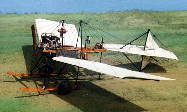
Anthony Fokker's Spider ("Spinne" in his native Dutch) was the first in a grand series of Fokker airplanes lasting more than 80 years. The first Spider took to the air in 1910, when young Anthony was only 20 years old. A strange and delicate looking machine, it was an attempt to build an inherently stable aircraft - something then very much in vogue with designers around the world. With its great dihedral and sweepback, it largely succeeded. By the standards of the day, the several members of Fokker's Spider family were fine performers, blasting through the sky at maybe 40mph powered by any one of several different engines from 50hp to 100hp. Evolving through many versions, the most successful was probably the Series III starting in 1911, using the Argus 50hp engine.
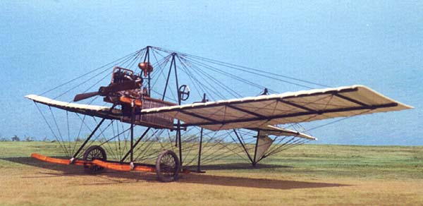 About 25 Spiders were built, and all varied in detail and exact dimensions,
each being hand made, but the overall design remained remarkably consistent.
The wings were single fabric surfaces with sewn-in pockets stretched over
ribs attached to external spars, as were the tail surfaces. Some machines
had ailerons and some had no roll control! A few Spiders were configured
to carry a passenger forward of the pilot. There really was no fuselage
as all major components - wings, tail, engine and fittings, and landing
gear were attached to two short lengths of wood. The real structural strength
came from the insanely complex maze of wires, giving the airplane its
name.
About 25 Spiders were built, and all varied in detail and exact dimensions,
each being hand made, but the overall design remained remarkably consistent.
The wings were single fabric surfaces with sewn-in pockets stretched over
ribs attached to external spars, as were the tail surfaces. Some machines
had ailerons and some had no roll control! A few Spiders were configured
to carry a passenger forward of the pilot. There really was no fuselage
as all major components - wings, tail, engine and fittings, and landing
gear were attached to two short lengths of wood. The real structural strength
came from the insanely complex maze of wires, giving the airplane its
name.
The Spider makes a fine starting point to measure just how far aviation would develop over the next eight years. By 1918, the Fokker company was mass producing airplanes that were only 2/3 the size, more than three times the horsepower and triple the performance!
Specs for typical Series III:
Span: 11m
Length: 7.75m
Engine: Argus 50hp water-cooled straight four cylinders
The Model
When I first applied my brain to the problems of building a 1/48 Spider, I thought "Hey - should be easy - no fuselage, no clear parts and no markings". I should have known better! As Lurch from the Addams Family would say "uuuuuuuuu"! The more I thought the more I realized that EVERYTHING would be hanging off two tiny sticks, and the only things initially keeping these sticks square and true would be a little brace at the rear, and the engine in the front. Mentally committed (insert own joke here!) I figured I'd best start with the engine!
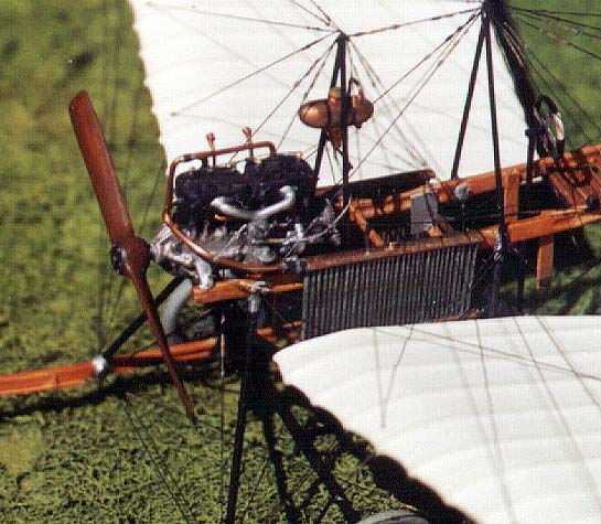
The Engine
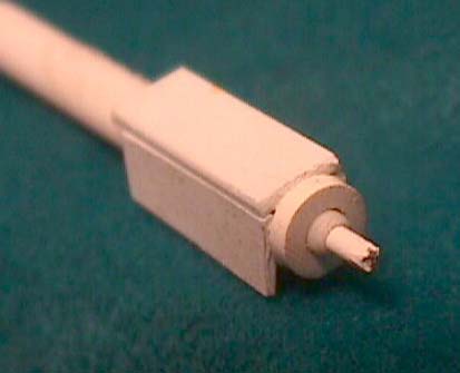 The small, four-cylinder Argus began as a Plastruc tube to hold the propeller
shaft and around this a crankcase was built up from heavy sheet plastic
- maybe .040"- I don't know! My methods are along the lines of "need a
piece, see a scrap, grab it and start hacking away". Some work with knife
and file and sandpaper got the basic shape and I was ready to pile on
the details. The two twin-cylinder banks were glued up from tubing with
the solid tops carved in place from built-up sheet. Once these were glued
onto the crankcase the tiny bits started to appear.
The small, four-cylinder Argus began as a Plastruc tube to hold the propeller
shaft and around this a crankcase was built up from heavy sheet plastic
- maybe .040"- I don't know! My methods are along the lines of "need a
piece, see a scrap, grab it and start hacking away". Some work with knife
and file and sandpaper got the basic shape and I was ready to pile on
the details. The two twin-cylinder banks were glued up from tubing with
the solid tops carved in place from built-up sheet. Once these were glued
onto the crankcase the tiny bits started to appear.
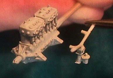
 The fine braces and fins cast into the real Argus crankcase were duplicated
with small triangles of CA-saturated typing paper. The external valve
pushrod and spring mechanisms were cut from wound guitar strings, partially
unwound, and the nuts and bolts were painted on with white glue.
The fine braces and fins cast into the real Argus crankcase were duplicated
with small triangles of CA-saturated typing paper. The external valve
pushrod and spring mechanisms were cut from wound guitar strings, partially
unwound, and the nuts and bolts were painted on with white glue.
 The intake manifold was done up from stretched and bent sprue with a carb
hashed out of bits of sliced tubing of various diameters. On any photos
of the real article, I could never spot anything resembling either an
exhaust manifold or individual pipes, so I assumed this engine just spat
its fumes into the cosmos directly from the cylinder head.
The intake manifold was done up from stretched and bent sprue with a carb
hashed out of bits of sliced tubing of various diameters. On any photos
of the real article, I could never spot anything resembling either an
exhaust manifold or individual pipes, so I assumed this engine just spat
its fumes into the cosmos directly from the cylinder head.
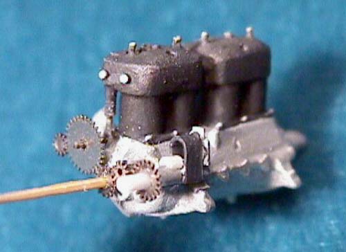 One thing I had never encountered in all my years of modeling was an external
array of gears quite like the conglomeration seen on the rear end of the
Argus! Luckily, I've never thrown away a busted watch in my life so I
have a coffee cup full of assorted watch guts, including some tiny gears!
The real problem was finding the correct sizes, my method here being to
dump the cup onto a big sheet of paper, grab a magnifying glass and start
comparing. Nine years later (well, it SEEMED like it!) I had my gears
and three minutes later the engine had them. CA glue all the way!
One thing I had never encountered in all my years of modeling was an external
array of gears quite like the conglomeration seen on the rear end of the
Argus! Luckily, I've never thrown away a busted watch in my life so I
have a coffee cup full of assorted watch guts, including some tiny gears!
The real problem was finding the correct sizes, my method here being to
dump the cup onto a big sheet of paper, grab a magnifying glass and start
comparing. Nine years later (well, it SEEMED like it!) I had my gears
and three minutes later the engine had them. CA glue all the way!
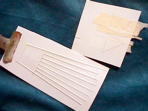
The wings
With the engine out of the way, my thoughts turned to the next difficult area - the wings. After thinking about and discarding a few ways of making them, I decided to vacuform them. Being single surface, the wings would be easy to do this way, but prevention of floppy-span syndrome might be a problem. I gambled that the external spars would prevent this and so I made my forms.
 The Spider's airfoil was almost flat except for a leading edge downward
curve and this made it easy. A little rounding off of the edge of a 1/4"
slab of balsa and the airfoil was established. This was sealed with multiple
coats of whatever paint I had hanging around that was on the verge of
going bad. Sanded slick, I glued the "rib pockets" over this using the
smallest Evergreen half-rounds I could find. A couple more coats of lousy
paint and I was ready to vac.
The Spider's airfoil was almost flat except for a leading edge downward
curve and this made it easy. A little rounding off of the edge of a 1/4"
slab of balsa and the airfoil was established. This was sealed with multiple
coats of whatever paint I had hanging around that was on the verge of
going bad. Sanded slick, I glued the "rib pockets" over this using the
smallest Evergreen half-rounds I could find. A couple more coats of lousy
paint and I was ready to vac.
 My vacuum forming machine is just a box made from scrap 1/4" plywood,
sealed with some kind of silicon plumbing putty. A bunch of holes are
drilled in the top, and a hole is cut in the side to take the nozzle of
a cheap shop-vac. My frame to hold the plastic is made from 3/4/"x3/4"
scrap, and the plastic is duct-taped to the frame.
My vacuum forming machine is just a box made from scrap 1/4" plywood,
sealed with some kind of silicon plumbing putty. A bunch of holes are
drilled in the top, and a hole is cut in the side to take the nozzle of
a cheap shop-vac. My frame to hold the plastic is made from 3/4/"x3/4"
scrap, and the plastic is duct-taped to the frame.
For the Spider, I used .010" sheet, heating this in the oven. When the plastic hit that very satisfying rubbery state, I grabbed it and quickly slammed it over the wing form while switching on the shop-vac. THUUUUCKPH! Few things in modeling are more satisfying than watching a piece of flabby plastic assume a desired shape as it's sucked over a vac-mold!
 After cooling a bit, I cut the wings from the sheet with scissors and
refined the leading and trailing edges. The Spider is one of the few airplanes
that not only needs scalloping along the trailing edge, but the leading
edge also. Having shaped my wings, I added the underside of the rib pockets
by gluing half-rounds up under each top pocket. Any gaps were filled with
whatever clear acrylic happened to be closest to my hand. Since these
wings would need to be translucent, I couldn't use regular fillers. The
real wings also had no treatments of any kind - no dope, varnish or paint,
and they were also probably made from bleached cloth, so I had to maintain
good clean wings with no flaws.
After cooling a bit, I cut the wings from the sheet with scissors and
refined the leading and trailing edges. The Spider is one of the few airplanes
that not only needs scalloping along the trailing edge, but the leading
edge also. Having shaped my wings, I added the underside of the rib pockets
by gluing half-rounds up under each top pocket. Any gaps were filled with
whatever clear acrylic happened to be closest to my hand. Since these
wings would need to be translucent, I couldn't use regular fillers. The
real wings also had no treatments of any kind - no dope, varnish or paint,
and they were also probably made from bleached cloth, so I had to maintain
good clean wings with no flaws.
 When my wings
were finished, they received only the lightest misting of airbrushed matte
white paint to brighten them up a little and kill the plastic sheen. The
steel tube spars and braces of the original were duplicated on the model
from bamboo skewers, shaved down to the correct diameter. I smeared CA
over these bits for extra strength and painted them black. After this
treatment, my spar stock was cut to size and the pieces stuck under each
wing with a TINY drop of CA at each rib station.
When my wings
were finished, they received only the lightest misting of airbrushed matte
white paint to brighten them up a little and kill the plastic sheen. The
steel tube spars and braces of the original were duplicated on the model
from bamboo skewers, shaved down to the correct diameter. I smeared CA
over these bits for extra strength and painted them black. After this
treatment, my spar stock was cut to size and the pieces stuck under each
wing with a TINY drop of CA at each rib station.
At this stage, I had to start considering the rigging and where to drill the multitude of holes along the wing and in the spars. After getting this figured out, I started drilling with my home-made bit made from a piece of .007" guitar string CA'd into a stub of bamboo, the mess being chucked up into my Dremel MiniMite.
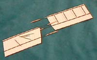
The Tail
 The tail surfaces were built the same way as the wings, except no vacuforming
was necessary. I cut the outline from .010" stock and stuck on the rib
pockets, top and bottom, from half-rounds. The vertical tail surfaces
had no pockets and were nothing more than .010" with the internal structure
masked and sprayed with white paint. This opaque white under the lightly
misted top coat white shows up quite nicely as a shadow inside the rudders
when backlit.
The tail surfaces were built the same way as the wings, except no vacuforming
was necessary. I cut the outline from .010" stock and stuck on the rib
pockets, top and bottom, from half-rounds. The vertical tail surfaces
had no pockets and were nothing more than .010" with the internal structure
masked and sprayed with white paint. This opaque white under the lightly
misted top coat white shows up quite nicely as a shadow inside the rudders
when backlit.
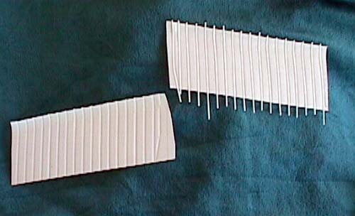
The Radiator
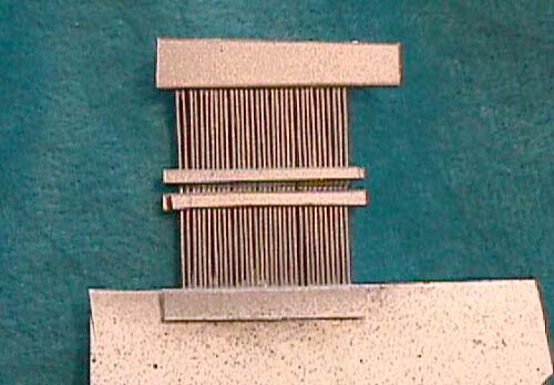 Now that the major components were out of the way, the next most difficult
task was the radiators. The technique was simple, but tedious. A bunch
of pieces were cut from the smallest diameter Evergreen rod I could find
and these were layed-up in a simple jig, building the two radiators together
as one unit, then cutting them apart and cleaning them up. Not difficult,
just tedious and boring! It was starting to look like this model might
turn into a viable project!
Now that the major components were out of the way, the next most difficult
task was the radiators. The technique was simple, but tedious. A bunch
of pieces were cut from the smallest diameter Evergreen rod I could find
and these were layed-up in a simple jig, building the two radiators together
as one unit, then cutting them apart and cleaning them up. Not difficult,
just tedious and boring! It was starting to look like this model might
turn into a viable project!
The "Fuselage"
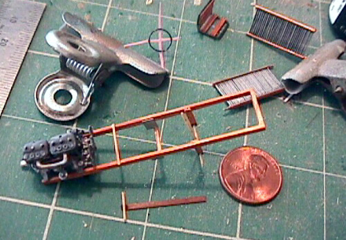 I needed my "fuselage" next so I could start hanging my sub-assemblies
on something. A couple of basswood sticks were routed out along the sides
as per the real items, stained with Future tinted to a golden reddish
brown and varnished with CA applied with a tape covered finger tip. Offered
up to lugs on the motor, the heart of the Spider was ready for festooning
with the remaining bits. The seat was a simple affair of bent wire and
slats, not unlike some kinds of patio furniture, the only thing I had
to watch out for was the width- this had to match exactly the inside width
of the "fuselage". Various other wooden braces and places for fittings
to hang were cut from basswood, given the Future and CA treatment and
stuck on.
I needed my "fuselage" next so I could start hanging my sub-assemblies
on something. A couple of basswood sticks were routed out along the sides
as per the real items, stained with Future tinted to a golden reddish
brown and varnished with CA applied with a tape covered finger tip. Offered
up to lugs on the motor, the heart of the Spider was ready for festooning
with the remaining bits. The seat was a simple affair of bent wire and
slats, not unlike some kinds of patio furniture, the only thing I had
to watch out for was the width- this had to match exactly the inside width
of the "fuselage". Various other wooden braces and places for fittings
to hang were cut from basswood, given the Future and CA treatment and
stuck on.
The Skids
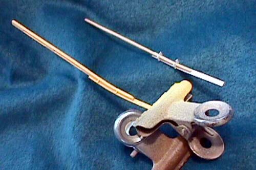 For the skids, I grabbed some bamboo skewers, shaved them into a rectangular
cross section and boiled them in a coffee cup in the microwave. I quickly
retrieved them and curved them in my fingers. It wasn't really THAT painful.
Since only the tips of the skids needed a curve, I duct-taped the ends
around the coffee cup and let them set overnight. The next morning the
skids had held their fine curve and all was well.
For the skids, I grabbed some bamboo skewers, shaved them into a rectangular
cross section and boiled them in a coffee cup in the microwave. I quickly
retrieved them and curved them in my fingers. It wasn't really THAT painful.
Since only the tips of the skids needed a curve, I duct-taped the ends
around the coffee cup and let them set overnight. The next morning the
skids had held their fine curve and all was well.
 The skid shoes were made from some kind of scrap styrene from a fast-food
cup lid - this stuff was thinner than .010" and thicker than .005". Glued
to the skid undersides and stained along with the bamboo bits, I had my
skids ready to mount on their forests of sticks and poles. These legs
were steel tubes on the real airplane and mine are made from shaved bamboo.
I assembled my two skid-and-leg units and stuck them to the fuselage,
with a couple of temporary braces lightly glued on to hold it all in place
as the project progressed. Putting it All Together
The skid shoes were made from some kind of scrap styrene from a fast-food
cup lid - this stuff was thinner than .010" and thicker than .005". Glued
to the skid undersides and stained along with the bamboo bits, I had my
skids ready to mount on their forests of sticks and poles. These legs
were steel tubes on the real airplane and mine are made from shaved bamboo.
I assembled my two skid-and-leg units and stuck them to the fuselage,
with a couple of temporary braces lightly glued on to hold it all in place
as the project progressed. Putting it All Together
The radiators were hung on tiny invisible pegs made from .007" guitar string.
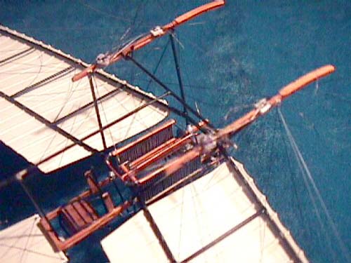 The wing mount tubes were next in line, and fear was building. If these
weren't perfect, the whole thing would be a skewed mess. The full size
Spider's wings were mounted by inserting the spar ends into a couple of
tubes bolted to the skid legs. Wishing to follow actual practice, I found
some plastic tube that was about the diameter of my spars. Cutting appropriate
lengths and bending a slight kink into each end of each tube, I had two
bent tubes that resembled sets of blunted cow horns. With careful shaving
on the spar ends and reaming of the tube ends, I got good sturdy matings.
After a coat of black paint, I glued my mount tubes to the legs and reinforced
the joints with a bit of wire wrapping using some stuff that's far thinner
than human hair- it's almost invisible. If I look closely, I can see it,
but I figured that this was a small price to pay for a bit of extra strength
in the most critical part of the model. With this part now thankfully
complete, I could add the last bits before it all came together.
The wing mount tubes were next in line, and fear was building. If these
weren't perfect, the whole thing would be a skewed mess. The full size
Spider's wings were mounted by inserting the spar ends into a couple of
tubes bolted to the skid legs. Wishing to follow actual practice, I found
some plastic tube that was about the diameter of my spars. Cutting appropriate
lengths and bending a slight kink into each end of each tube, I had two
bent tubes that resembled sets of blunted cow horns. With careful shaving
on the spar ends and reaming of the tube ends, I got good sturdy matings.
After a coat of black paint, I glued my mount tubes to the legs and reinforced
the joints with a bit of wire wrapping using some stuff that's far thinner
than human hair- it's almost invisible. If I look closely, I can see it,
but I figured that this was a small price to pay for a bit of extra strength
in the most critical part of the model. With this part now thankfully
complete, I could add the last bits before it all came together.
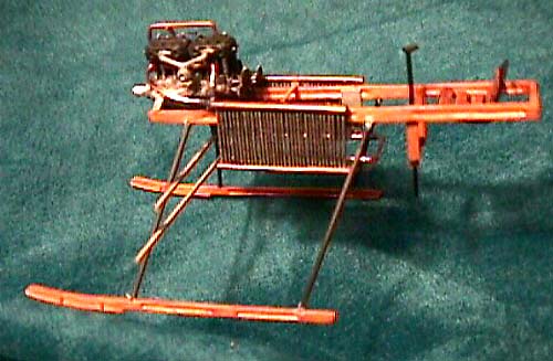
 I wedged the seat in between the "fuselage" sticks and then tackled the
radiator plumbing with a bit of heavy copper wire. More wire for the control
wheel on its bamboo stick, a rudder bar from wood, and the overhead inverted
"v" brace with its fuel tank of turned plastic rod - the usual stuff -
these led me to a point where I had to stop and think. If I put the wings
on, I'll need to do some rigging, and this is a great target for snagging.
If I do the tail feathers next - same thing. What next? What next? What
can I do that has the least risk of being screwed up by yours truly before
the beast is finished?
I wedged the seat in between the "fuselage" sticks and then tackled the
radiator plumbing with a bit of heavy copper wire. More wire for the control
wheel on its bamboo stick, a rudder bar from wood, and the overhead inverted
"v" brace with its fuel tank of turned plastic rod - the usual stuff -
these led me to a point where I had to stop and think. If I put the wings
on, I'll need to do some rigging, and this is a great target for snagging.
If I do the tail feathers next - same thing. What next? What next? What
can I do that has the least risk of being screwed up by yours truly before
the beast is finished?
'Spinning' the web
 Deciding the tail was a smaller target, I mounted the horizontal unit.
The only real point of attachment is along the leading edge to the little
cross brace at the "fuselage" rear! A mass of wires does the rest. Oh
well, nothing to do but get on with it! With the unit glued to its cross
brace, I started rigging, and what had seemed daunting was starting to
become enjoyable. Since my rigging was structural, it was fun to tweek
and pull the wires this way and that and watch the tail start to line
up and become true. All rigging here and throughout the entire model was
done with so-called invisible thread, really fine nylon mono. All thread
was anchored with CA.
Deciding the tail was a smaller target, I mounted the horizontal unit.
The only real point of attachment is along the leading edge to the little
cross brace at the "fuselage" rear! A mass of wires does the rest. Oh
well, nothing to do but get on with it! With the unit glued to its cross
brace, I started rigging, and what had seemed daunting was starting to
become enjoyable. Since my rigging was structural, it was fun to tweek
and pull the wires this way and that and watch the tail start to line
up and become true. All rigging here and throughout the entire model was
done with so-called invisible thread, really fine nylon mono. All thread
was anchored with CA.
After this success, the fear over the wings was starting to lessen.
Sticking the spar ends into the tube mounts and rigging from the inside
out gave me a super strong structure. My worries had all been for naught!
It was all very methodical and no extremely unusual  care was taken to avoid damage to the already completed areas. I could
explain every wire but if someone attempts this or a similar project,
they'll find that the order is almost self-dictating. A few runs required
a test try to see that some other wire wasn't going to be crossed, but
even these were few. The rigging WAS time consuming, but its internal
logic kept the brain-drain to a minimum. Anthony Fokker knew what he was
doing!
care was taken to avoid damage to the already completed areas. I could
explain every wire but if someone attempts this or a similar project,
they'll find that the order is almost self-dictating. A few runs required
a test try to see that some other wire wasn't going to be crossed, but
even these were few. The rigging WAS time consuming, but its internal
logic kept the brain-drain to a minimum. Anthony Fokker knew what he was
doing!
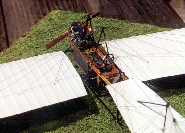
I rested a bit before the final push, newly inspired. I found a prop in the scrap box and reshaped it and popped it on the prop shaft and then turned my attention to the landing gear. A couple of Eduard brass spoked wheels forced to fit in a couple of rubber "o" rings and I was into the final lap. I added an axle of shaved bamboo and a couple more braces in the skid and landing gear forest. The rather large and very multitudinous turnbuckles were "painted" on with a mix of white glue and acrylic craft paint and touched up with a bit of silver and brass paint and the monster was done........or so I thought.
 The model looked pretty good, but with all the small details encrusted
upon it, I was afraid that the least bit of handling was going to be a
dangerous activity. The overall strength was high, but these vulnerable
detail bits were starting to worry me. This model was also almost weightless.
Its mass was so slight that someone across the room could sneeze and it
might jump off the table. OK, I thought, I'll build a base to mount the
little monster on, but I want to make the model removable. Hmmm....maybe
some kind of peg up through the wheels?
The model looked pretty good, but with all the small details encrusted
upon it, I was afraid that the least bit of handling was going to be a
dangerous activity. The overall strength was high, but these vulnerable
detail bits were starting to worry me. This model was also almost weightless.
Its mass was so slight that someone across the room could sneeze and it
might jump off the table. OK, I thought, I'll build a base to mount the
little monster on, but I want to make the model removable. Hmmm....maybe
some kind of peg up through the wheels?
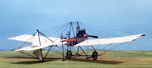
Display Base
 Taking a great risk, I hoped and prayed that I had enough skill to DRILL
up through the already mounted tires with my trusty homemade .007" bit.
This I did! All was well so I went ahead and landscaped and finished my
base using chopped macramé yarn for the grass, stuck on with matte acrylic
medium and airbrushed in various shades of yellow, brown, green and tan.
To accommodate my mounting pegs, I drilled into the base, again with the
homemade bit and glued two small sections of guitar string, one under
each wheel location, the little dudes standing proud by a hair less than
the thickness of the tire they would be smothered by. Knowing that these
little pegs would be almost impossible to find in the fake grass, I touched
the top of each with a spot of day-glo orange! A deep breath, a short
prayer and a few moments for my eyes to focus so tightly and I was ready
to test fit the model's wheels over the pegs............Bingo! A tight
fit, and the Spider now had a secure resting place!
Taking a great risk, I hoped and prayed that I had enough skill to DRILL
up through the already mounted tires with my trusty homemade .007" bit.
This I did! All was well so I went ahead and landscaped and finished my
base using chopped macramé yarn for the grass, stuck on with matte acrylic
medium and airbrushed in various shades of yellow, brown, green and tan.
To accommodate my mounting pegs, I drilled into the base, again with the
homemade bit and glued two small sections of guitar string, one under
each wheel location, the little dudes standing proud by a hair less than
the thickness of the tire they would be smothered by. Knowing that these
little pegs would be almost impossible to find in the fake grass, I touched
the top of each with a spot of day-glo orange! A deep breath, a short
prayer and a few moments for my eyes to focus so tightly and I was ready
to test fit the model's wheels over the pegs............Bingo! A tight
fit, and the Spider now had a secure resting place!
The Spider looks like nothing else, and makes an interesting companion when placed next to a Fokker D.VII or triplane. There are few things I would do differently if I had to make another one of these arachnoidal dainties, but now that I've done this one, I hope I never have to do another!
Sources
Air Trails, Spring 1977 featured a long and very extensive article by Eldon Quick on the entire Spider family, including some well done, complex and complete drawings by Mr. Quick himself, based on information obtained from the Fokker archives and bits and pieces of remaining airframes. The engine details were obtained mainly from several assorted issues of WW I Aero.