
This article originally appeared in the January 2000 issue of Internet Modeler.
 Building
the Passchendaele 1/48 resin
Building
the Passchendaele 1/48 resin
Halberstadt D.III
By Steve Perry
[Editor's note - Steve was given one of the first pre-production kits to build and as such it was lacking in detail parts that the actual kit will contain. For a review of the actual kit see my review in the next issue – RNP.]
The Halberstadt Fighters
The Halberstadt D.II was the first German biplane fighter to enter air combat. It did so in June of 1916 just prior to the opening of the Battle of the Somme. Developed from the Halberstadt B.I and B.II trainers, the 120 hp Mercedes- powered D.II, and the 120 hp Argus-powered, D.III proved an answer to the French Nieuports and British Dh3s that were dominating the less maneuverable Fokker Eindeckers.
It was Halberstadt fighters from which the first German air-to-air rockets were launched. In 1917, the Versuchsabteilung Staffel flew Halberstadt fighters equipped with air-to-air wireless communications and was the first unit to experiment with the tactics made possible by communication between aircraft in a flight. After being outclassed by superior Allied fighters, Halberstadt fighters served as advanced trainers and with units in Palestine as well as with the Ottoman Air Force. These Turkish Halberstadts were the D.V variant.
In a report some six weeks after the first eight Halberstadts appeared over the Western Front, the commander of the German Air Service wrote, "The D Type fighter which came to the front several weeks ago, has proved superior not only with respect to speed and rate of climb, but also in maneuverability. It will replace the E Type; the conversion has begun."
Building the Passchendaele Halberstadt D.III
Let me begin by stating that this is a 'Builder's kit'. It is not an 'Assembler's kit'. A kit may take time to assemble, but it requires more time to build a model. For those modelers who enjoy the process of building models, this will be a satisfying project.
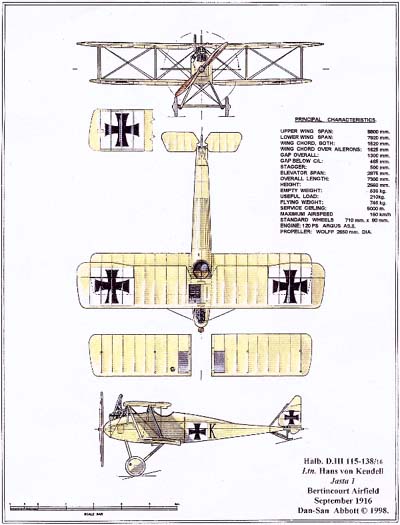
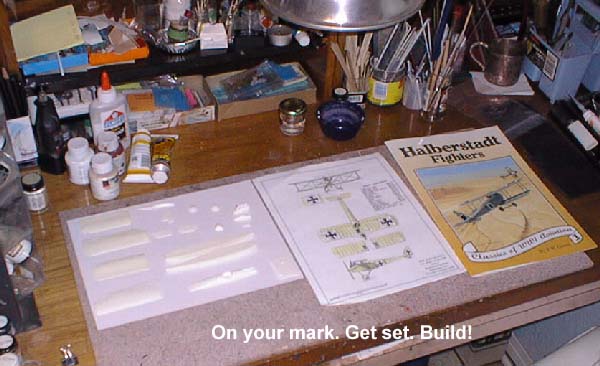
 With
no references other than the kit's beautiful Dan-San Abbot three view
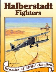
depicting the D.III , the first thing I did was to order the Halberstadt
Fighters book by Peter Grosz from Roll Models. This book is up to the
usual high standards of Albatros Publications and is an indispensable
aid to modeling these aircraft.
With
no references other than the kit's beautiful Dan-San Abbot three view
depicting the D.III , the first thing I did was to order the Halberstadt
Fighters book by Peter Grosz from Roll Models. This book is up to the
usual high standards of Albatros Publications and is an indispensable
aid to modeling these aircraft.
This is my first attempt at building a full resin kit, so if you haven't built one yet either, read on and learn from my mistakes.
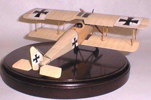
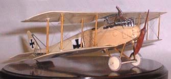
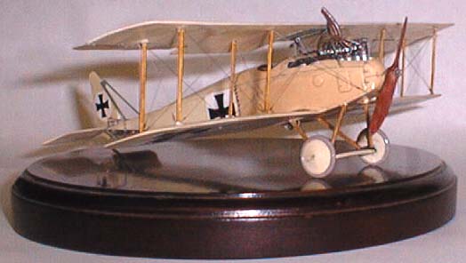
I was given a set of resin pieces packaged in the typical Passchendaele segmented plastic bag. This is fairly thick clear plastic sheet that has been divided into 'pockets.' A few similar pieces are sealed into each pocket. This way they receive the maximum protection, yet are also very easy to view. Included with the resin pieces were two Dan-San Abbot color three views. One of the D.II and one of the D.III flown by Hans von Keudell of Jasta 1. I chose to build my kit as von Keudell's D.III in a CDL finish. Halberstadt fighters with visible serial numbers are rare, so I have no information past the range of serials given on the three view, (D.III 115 - 138/16 ).
 The
parts are cast in Passchendaele's beautiful 'white chocolate' resin. They
look good enough to eat. I proceeded to clean up the parts and in so doing
learned about resin. The resin parts look like they are surrounded by
the 'flash from hell,' but it cleans up very easily. In fact extreme caution
needs to be exercised when trimming and sanding resin pieces. They cut
and sand very easily and if you attack them with the same gusto as you
would a similar injection molded piece of styrene, you can easily overdo
the job and hurt the part. Fortunately I did no damage and the parts cleaned
up easily.
The
parts are cast in Passchendaele's beautiful 'white chocolate' resin. They
look good enough to eat. I proceeded to clean up the parts and in so doing
learned about resin. The resin parts look like they are surrounded by
the 'flash from hell,' but it cleans up very easily. In fact extreme caution
needs to be exercised when trimming and sanding resin pieces. They cut
and sand very easily and if you attack them with the same gusto as you
would a similar injection molded piece of styrene, you can easily overdo
the job and hurt the part. Fortunately I did no damage and the parts cleaned
up easily.
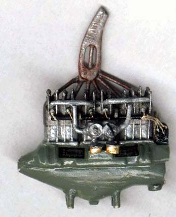
BUILDING THE ENGINE
 I began
with the engine. Passchendaele's Master Modeler, Scott Scarborough, has
provided a very good basic engine which has been replicated by Passchendaele's
Master Caster, John Cyganowski. There are three pieces. The top and bottom
pieces are split along the crankshaft center and there is an exhaust stack.
The top piece is the upper case, the cylinders and the valve springs.
These have some neat representations of the springs. On my example they
were not separate, but in pairs. I used a fine jewelers saw to (very carefully
with this resin stuff!) separate the pair atop each cylinder. The two
engine halves need the extra thickness of the resin 'sheet' on which they
came to be sanded off.
I began
with the engine. Passchendaele's Master Modeler, Scott Scarborough, has
provided a very good basic engine which has been replicated by Passchendaele's
Master Caster, John Cyganowski. There are three pieces. The top and bottom
pieces are split along the crankshaft center and there is an exhaust stack.
The top piece is the upper case, the cylinders and the valve springs.
These have some neat representations of the springs. On my example they
were not separate, but in pairs. I used a fine jewelers saw to (very carefully
with this resin stuff!) separate the pair atop each cylinder. The two
engine halves need the extra thickness of the resin 'sheet' on which they
came to be sanded off.
I just love detailing engines and cockpits, so to me, this is an ideal kit engine. The Argus As.II drawings in the Halberstadt book show all the engine detail I could ever use and plenty more too.
I opened a hole where each spark plug needed to be and then CAed a piece of 30 thou rod in the hole. When set, I nipped the rod close and then trimmed it just proud of flush with a sharp #11 blade. This will be the base of each plug.
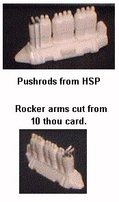
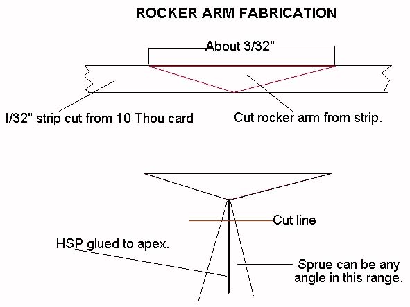
Next were the rocker arms. These I cut out of 10 thou card. Just flattened triangle shapes. Then come the fulcrum supports for the rockers. I used a piece of fine heat-stretched sprue, (HSP), dipped the end in a puddle of CA and carefully stick it on the apex of one of the rocker arm triangles. A bit of fiddling and it's in place. The rockers will sometimes set at a bit of an angle on the sprue. Good, some rocker ends are up and some are down depending on where it is in the firing order. I trimmed the tops of the springs to different heights. I didn't know the Argus As.2 firing order and wouldn't have known which valve springs would be compressed even if I had the correct firing order, so I mixed up the compressed and uncompressed springs until they looked good to me. (I try to keep this on the 'hobby' side of 'obsession').
 I
nipped the sprue attached to the apex to about 1/32" or less. A drop of
CA on top of the valve spring and one end of the rocker arm set atop the
spring. If the spring is compressed the opposite end of the arm goes up
and vice versa. Be sure to place the rockers to the outside edge of the
spring to provide sufficient space between, as the intake manifold pipe
for each cylinder goes between the pushrods for that cylinder. Pushrods
are from HSP. Dip one end in a puddle of CA and stick it to the case directly
below the rocker arm. When it sets, pull it taught across the end of the
rocker arm and touch it with a tiny drop of CA. Trim the loose end flush
when it all sets up.
I
nipped the sprue attached to the apex to about 1/32" or less. A drop of
CA on top of the valve spring and one end of the rocker arm set atop the
spring. If the spring is compressed the opposite end of the arm goes up
and vice versa. Be sure to place the rockers to the outside edge of the
spring to provide sufficient space between, as the intake manifold pipe
for each cylinder goes between the pushrods for that cylinder. Pushrods
are from HSP. Dip one end in a puddle of CA and stick it to the case directly
below the rocker arm. When it sets, pull it taught across the end of the
rocker arm and touch it with a tiny drop of CA. Trim the loose end flush
when it all sets up.
The spark plugs begun earlier were completed by sticking a piece of HSP in the center of each 'base' and when set, trimming it off just past the pushrods. A tiny drop of CA or white glue on the HSP plug will give it body and strength.
The plug wire conduit is made of 30 thou rod. Thin strips, (1/64") of five thou card are glued at right angles and spaced to fit between the cyl banks. This is trimmed about 3/64" in length and the conduit attached directly below the plugs. On the pushrod side, it is outside the rods.
Semicircular plug leads were made from copper armature wire wound around a piece of rod. The resulting 'spring' is slid off onto a hard surface and the tip of an Xacto knife is slid inside the coil and the coil cut from the inside. This makes a pile of little rings. (As an aside, this is how chain mail was made in the Middle Ages) Cut in half, the rings match the photos of the Argus engine in the datafile.
Six holes were drilled in each magneto. Copper armature wire was CAed into each hole. The wires were trimmed and bent to meet the rear end of the plug wire conduit.
The intake manifold was made of bent 30 thou rod. The carbs were fashioned from bits of sprue and some discs punched from 10 thou card.
The exhaust manifold looked like a major challenge, but turned out to be much tamer. Scott of Passchendaele put six dimples in the very end of the resin exhaust stack. These I drilled out and then inserted bits of 25 thou rod. These were trimmed and bent to fit to the engine.
 I
found out that resin doesn't drill as clean a hole as styrene, When drilling
in the #70 - #80 range, the holes in resin retain more "fuzz" and are
harder to clean out than similar holes in styrene. Also, extreme care
needs to be taken when opening the exhaust end of the stack. The resin
is delicate stuff.
I
found out that resin doesn't drill as clean a hole as styrene, When drilling
in the #70 - #80 range, the holes in resin retain more "fuzz" and are
harder to clean out than similar holes in styrene. Also, extreme care
needs to be taken when opening the exhaust end of the stack. The resin
is delicate stuff.
The basic engine is there and the details are easy to add to it. As a modeling friend puts it, "Every modeler will rise to his own level of masochism." It took a week of evenings to do this engine and it looks better than the scans from normal viewing distance. The sprue, rod and card I made the detail bits from were easier to work with than PE. I think Passchendaele has hit on the right idea with the engine. I had all the fun of working with the fiddly bits plus the satisfaction of having scratched the details myself.
DETAILING THE FUSELAGE INTERIOR
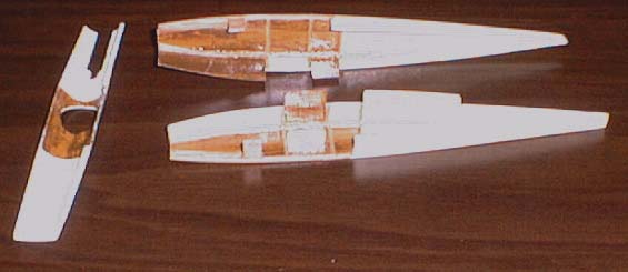
 The
best thing about Passchendaele's Halberstadt D.III cockpit is what is
not there. Specifically, thick walls and flooring. The casting of the
fuselage halves is almost vac like in thickness. The turtledeck piece
is thinner than most vacs. Whether this is intentionally one of the finest
examples of cast resin ever or just a result of John's New England Yankee
frugality with expensive resin doesn't matter. The pieces are thin and
flexible and there is all kinds of room in the interior for cockpit details.
The interior wooden frame is molded into the two fuselage halves and is
the only interior detail provided.
The
best thing about Passchendaele's Halberstadt D.III cockpit is what is
not there. Specifically, thick walls and flooring. The casting of the
fuselage halves is almost vac like in thickness. The turtledeck piece
is thinner than most vacs. Whether this is intentionally one of the finest
examples of cast resin ever or just a result of John's New England Yankee
frugality with expensive resin doesn't matter. The pieces are thin and
flexible and there is all kinds of room in the interior for cockpit details.
The interior wooden frame is molded into the two fuselage halves and is
the only interior detail provided.
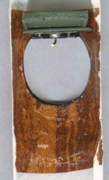
 Before
adding any of the details, the molded-in frame members were painted a
wood color and woodgrain decal was applied to the walls between the frame
members. The rear was painted CDL. There were no bracing wires on the
ply-covered part so I only added HSP bracing wires to the first fabric-covered
bay of which a small part can be seen behind the seat.
Before
adding any of the details, the molded-in frame members were painted a
wood color and woodgrain decal was applied to the walls between the frame
members. The rear was painted CDL. There were no bracing wires on the
ply-covered part so I only added HSP bracing wires to the first fabric-covered
bay of which a small part can be seen behind the seat.
I used 5 thou card covered with woodgrain decal for the floor panels. These I also used as alignment/glue tabs. I alternated sides, but if you should choose to do similar floor panels then I'd recommend gluing them all to the same side.
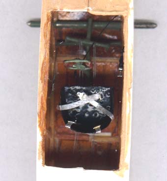 I
used a Toms Modelworks PE brass detail set '1:48 German Interiors'. From
this, I took the seat, throttle quadrant, air pump handle, three bezels
and some levers. The joystick/rudder bar assembly I scratched out of wire,
sprue and paper strip. The switch panel and ammo box were scratched to
look like the photos in the datafile.
I
used a Toms Modelworks PE brass detail set '1:48 German Interiors'. From
this, I took the seat, throttle quadrant, air pump handle, three bezels
and some levers. The joystick/rudder bar assembly I scratched out of wire,
sprue and paper strip. The switch panel and ammo box were scratched to
look like the photos in the datafile.
I incorporated the steel wire carry through, which supports the lower wing panels, with the rudder bar / joystick assembly so it is hidden in plain sight.
Seatbelts and buckles are Reheat items. The seat cushion is made of acrylic gel blackened with india ink. This is spread on a 3 x 5 card and as it dries the 'buttons' are made by pressing in with a toothpick. When dry the seat cushion is cut out and applied to the brass seat.
ASSEMBLING THE FUSELAGE
With the addition of the floorboards/alignment tabs, the fuselage fit together well and was easy to assemble. I glued my two pieces together right at the cockpit. There was a slight warp to the pieces at the tail and nose. Once the area around the cockpit had set, I worked toward the tail gluing and pressing together. The flexible pieces lined right up and fit well. Same as I worked toward the nose. The seams took a bit of sanding, but were as good as the average injection-molded kit with the added benefit that the resin works down easier than styrene. Work carefully to match the seams as exactly as you can. The pieces are very thin and you want to minimize the sanding.
 Careful
positioning of the turtle deck piece is needed so refer to drawings before
gluing. Also do the best job of feathering the joint between the rear
edge of the turtledeck and the top of the rear fuselage before you glue
the turtle deck in place. Again I first glued in the cockpit area and
let it set. Then I worked to the rear. The wonderfully thin turtledeck
is quite flexible and the dimensions are right on for a good fit with
the joined fuselage halves. I left the cowl pieces around the engine loose
until I had mounted the engine. If you use the floorboard tabs, then be
sure to trim the front 'feet' of the engine by their thickness.
Careful
positioning of the turtle deck piece is needed so refer to drawings before
gluing. Also do the best job of feathering the joint between the rear
edge of the turtledeck and the top of the rear fuselage before you glue
the turtle deck in place. Again I first glued in the cockpit area and
let it set. Then I worked to the rear. The wonderfully thin turtledeck
is quite flexible and the dimensions are right on for a good fit with
the joined fuselage halves. I left the cowl pieces around the engine loose
until I had mounted the engine. If you use the floorboard tabs, then be
sure to trim the front 'feet' of the engine by their thickness.
The nose bowl can be hollowed out and/or the front of the crankcase trimmed to fit. I ended doing a bit of each. Careful filling and sanding of the fuselage completes the basic structure.
PAINTING THE FUSELAGE
 After
sanding and polishing the bare resin, I masked the engine and cockpit
with Parafilm. Next I sprayed an overall primer coat of Testors Model
Master Radome Tan. This showed up all manner of imperfections, which I
worked out with CA and sanding. Then I touched up the sanded areas with
more Radome Tan from the airbrush. When that dried, I masked the front
with Parafilm and sprayed the back with Model Master Light Ivory. The
Radome Tan is not dark enough in tone to match the DF photos of CDL D.IIIs,
so I made up some tinted Future and handpainted 2 coats over the front
to darken it a bit. When that all dried well, I sprayed a couple of light
coats of straight Future over the whole thing. When that had set real
well, I used a watercolor pencil to highlight the turtledeck stringers
and blended that with Future for a subtle highlight of the stringers.
A little india ink wash around the panels and inspection plates and that
about finished the fuselage paint job.
After
sanding and polishing the bare resin, I masked the engine and cockpit
with Parafilm. Next I sprayed an overall primer coat of Testors Model
Master Radome Tan. This showed up all manner of imperfections, which I
worked out with CA and sanding. Then I touched up the sanded areas with
more Radome Tan from the airbrush. When that dried, I masked the front
with Parafilm and sprayed the back with Model Master Light Ivory. The
Radome Tan is not dark enough in tone to match the DF photos of CDL D.IIIs,
so I made up some tinted Future and handpainted 2 coats over the front
to darken it a bit. When that all dried well, I sprayed a couple of light
coats of straight Future over the whole thing. When that had set real
well, I used a watercolor pencil to highlight the turtledeck stringers
and blended that with Future for a subtle highlight of the stringers.
A little india ink wash around the panels and inspection plates and that
about finished the fuselage paint job.
TAILFEATHERS
 Here
is a classic example of "Do what I didn't". The Halberstadt had a full
flying horizontal tail and rudder. The horizontal tailplanes were joined
by a single steel tube spar and rotated around this when the control cables
were pulled. The rudder has a similar pivotal member. Its upper end forms
a tripod with two supporting members.
Here
is a classic example of "Do what I didn't". The Halberstadt had a full
flying horizontal tail and rudder. The horizontal tailplanes were joined
by a single steel tube spar and rotated around this when the control cables
were pulled. The rudder has a similar pivotal member. Its upper end forms
a tripod with two supporting members.
I used 30 thou styrene rod butt glued to represent the steel tube members. Not recommended. The pieces are too fine for me to drill into on an edge, so I recommend you open a tiny notch, (less than 1/16"), exactly where the tube members exit the horizontal tailplanes and the rudder. Cut the rod, brass might work better than styrene, just enough longer than necessary so it fits into and fills the notches. A drop of CA and some sanding will disappear the joint. As I said, "Do what I didn't".
Attaching the Halberstadt's tail surfaces requires a bit more patience than on some other designs, but you don't have to separate fin from rudder or stab from elevator, dress and paint the edges and reattach them in a properly deflected position. All in all the Halberstadt's tail group is not more difficult to model, just different and certainly more delicate looking than most.
Control horns are brass from the Tom's fret and the control cables are HSP.
JOINING THE TOP WING PANELS
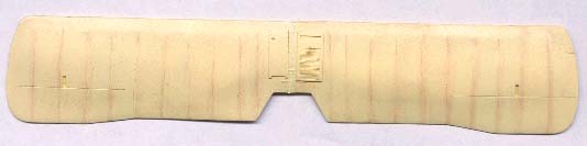 Passchendaele's
lovely, thin casting of the wing panels should not be a challenge to join.
I managed to make it one by finishing the panels before I joined them.
There are two dimples in the root edge of each panel. I drilled each carefully
with a #80 bit for a few millimeters. I cut short lengths of wire that
fit exactly in the hole and inserted them and CAed it all together. There
was a very minor difference in chords between the panels, due in large
part to my missing a bit of extra resin in my cleanup of the part. If
my panels hadn't already been painted, a couple of licks with a sanding
stick would have made the problem moot. I am clearly my own worst enemy,
but modeling wouldn't be as fun without me.
Passchendaele's
lovely, thin casting of the wing panels should not be a challenge to join.
I managed to make it one by finishing the panels before I joined them.
There are two dimples in the root edge of each panel. I drilled each carefully
with a #80 bit for a few millimeters. I cut short lengths of wire that
fit exactly in the hole and inserted them and CAed it all together. There
was a very minor difference in chords between the panels, due in large
part to my missing a bit of extra resin in my cleanup of the part. If
my panels hadn't already been painted, a couple of licks with a sanding
stick would have made the problem moot. I am clearly my own worst enemy,
but modeling wouldn't be as fun without me.
SEAM STITCHING
 The
Halberstadt fighters had more than the average amount of fuselage fabric
stitching. This needs to be represented in order to achieve an accurate
model of a Halberstadt. Passchendaele provided me with some Archer Fine
Transfer fuselage stitching, (German style). This product is a dry transfer
that is three dimensional when applied. The instructions say you can apply
it directly to the model or you can apply it to a strip of decal material
and apply that to the model.
The
Halberstadt fighters had more than the average amount of fuselage fabric
stitching. This needs to be represented in order to achieve an accurate
model of a Halberstadt. Passchendaele provided me with some Archer Fine
Transfer fuselage stitching, (German style). This product is a dry transfer
that is three dimensional when applied. The instructions say you can apply
it directly to the model or you can apply it to a strip of decal material
and apply that to the model.
I tried both methods and found that applying the transfer to a piece of decal material and coating that with an airbrushed coat of Micro Scale Clear Decal Film worked best for me.
After some more trials I developed the following steps to making a stitched seam:
1. Apply a row of stitches to a piece of clear decal material as per the transfer instructions.
2. With fine scissors, trim the row of stitches as close as possible.
3. Make a SINGLE clean cut with a NEW blade on the surface to precisely represent the actual seam.
4. Apply india ink to the cut mark with a fine brush.
5. Blot to a single fine line with Q-tips.
6. Apply the decal strip with the stitching over the inked seam line.
7. Coat with Future when dry.
Once on the decal material, the tops of the stitches can be painted any color with a very fine pointed brush. I left my stitches black which is probably the incorrect color, Although on a CDL finish I expect, and the few poor photos available indicate, that the stitching was darker but not jet black. On painted schemes the stitching needs to be added before painting as the stitching would have been painted over on the full size aircraft.
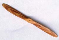 Propeller
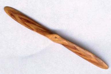
The resin propeller cleaned up well after removal from the resin backing it came on. I painted it a coat of acrylic paint mixed to a light wood shade with Raw Siena and Unbleached Titanium. When this had dried well I carefully marked the dark laminations with a watercolor pencil. This was blended with a damp Q-tip. Several mark/ blend cycles were required. I added a brass prop boss and a bit of drilled-out rod for the shaft. I do not believe in moving parts on static models, so the prop was simply glued in place on the model.
Wheels
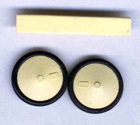 The
resin wheels that come with the kit appear to be very accurate and they
are nicely molded. The back needs sanding to remove the carrier material.
Tires are made from O-rings; two widths are supplied, so use the narrower
kind.
The
resin wheels that come with the kit appear to be very accurate and they
are nicely molded. The back needs sanding to remove the carrier material.
Tires are made from O-rings; two widths are supplied, so use the narrower
kind.
Struts
I made struts out of bamboo. This is an ideal strut material in my opinion. It is stronger than an injection, resin, extruded plastic stock or PE part the same size. Look in the housewares section of your grocery store and you will find several sizes of bamboo skewers available. I take the ones that are an 1/8" or 3/16" in diameter and split them down the middle lengthwise. Bamboo splits with great ease making two sticks of semicircular cross section. I then whittle the curved side to make a flat 'plank', I sand the planks smooth on both sides until it is the thickness of the strut. This makes my basic strut stock. I cut the strut blanks about 1/16" longer than actual size. From these blanks I shape the final strut with knife and sanding stick.
Once shaped I make a cutting jig. This is two pieces of masking tape on a cutting board exactly one strut length apart. To pin or not pin the struts is a matter of personal taste. To pin them, drill a very tiny hole (#80) into the end of the strut. Insert a bit of brass wire and CA. Nip the wires to 1/32" or less above or below the strut end. Drill a receiving hole in the wing. (Note, I said IN not THROUGH).
Finish the struts with Testors Wood and when dry mark them up a bit with some brown and yellow watercolor pencils and blend gently with a damp Q-tip or Future on a small brush. When fully dry, coat with clear Future before assembly.
Bamboo has one shortcoming and that is that drilling small rigging holes in the strut ends doesn't work well. It can be done, but it is very easy to slip and mess up the end of the strut and once drilled, the holes are hard to keep open.
 Rigging
I rig with heat-stretched sprue painted prior to installation. I made turnbuckles by placing a small amount of acrylic gel medium on the HSP where the turnbuckle is supposed to be. When dry I painted the turnbuckles brass.
Decals
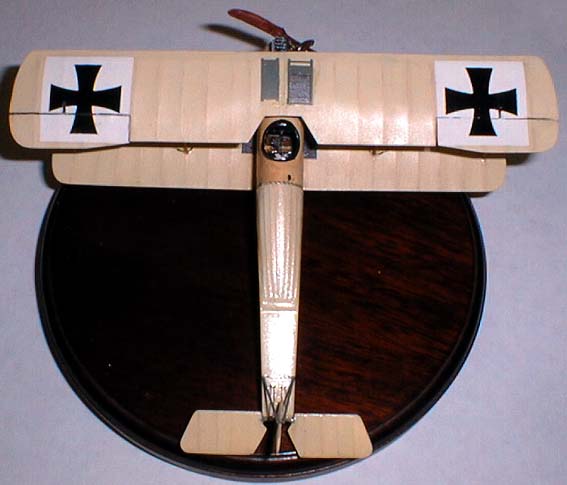
Although Bob Pearson has designed some decals for the D.III, these were not availabe for use at the time, therefore I used Americal/Gryphon crosses on my model.
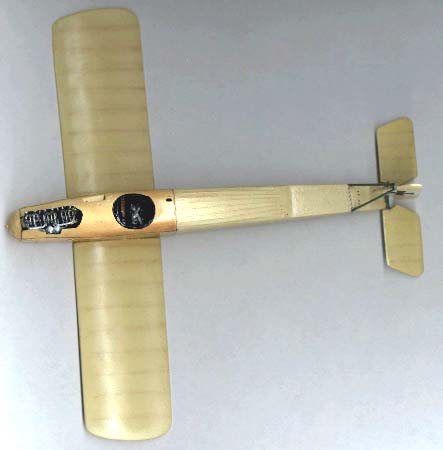
Summary
 I
had fun building this kit. It is definitely not a 'Shake the Box' kit.
This is a PLUS! In my book. The pieces fit together, most important locations
are marked accurately and the only modification necessary to a kit part
was some surgery on the cowl to get it to fit around my oversize scratch-
built carbs. The pieces that I had to make in order to complete the model
were pieces I would normally make myself even if the kit had provided
those parts.
I
had fun building this kit. It is definitely not a 'Shake the Box' kit.
This is a PLUS! In my book. The pieces fit together, most important locations
are marked accurately and the only modification necessary to a kit part
was some surgery on the cowl to get it to fit around my oversize scratch-
built carbs. The pieces that I had to make in order to complete the model
were pieces I would normally make myself even if the kit had provided
those parts.
I had lots of fun building the kit and I was rewarded with a fine model of an important and under represented aircraft. I heartily recommend Passchendaele's Halberstadt to anyone who has built a few WWI models .
The Passchendaele Halberstadt D.III will be followed by a D.II and a D.V.