
This article originally appeared in the August 2000 issue of Internet Modeler.
 Copper
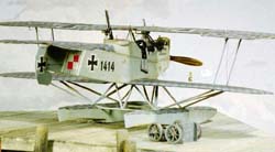
State Model's 1/48 Brandenburg W.12
Copper
State Model's 1/48 Brandenburg W.12
by Lance Krieg
Introduction
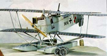
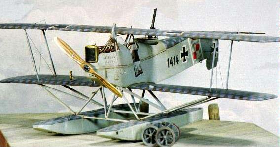
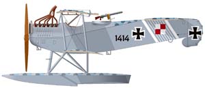
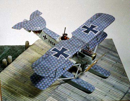
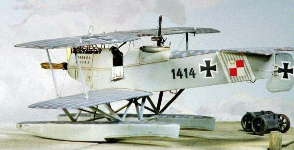
Copper State Models' excellent 1/48 multi-media kit of the Imperial German Navy's 'Kamel' offers a solid basis for an accurate reproduction. Because there were considerable variations in the 146 planes built, one must decide early in the construction which particular aircraft to depict. I chose 1414, the mount of Leutnant Becht of the seaplane station at Zeebrugge, as it would have looked shortly after delivery in December of 1917. 1414 was a short-fuselaged version with the early cabane strut arrangement, powered by the 150 HP Benz Bz.III.
References are scant; the Windsock Datafile offers the largest collection of photo images available, but there are still plenty of opportunities to scratch one's head and ponder.
Construction
 I
began construction by using my Mototool in a drill press to grind the
rear cockpit to a depth more nearly to scale, and locating the cabane
strut attachment points within the fuselage; these are not necessarily
obvious, particularly on early examples. It seems to this author that
the aft center section struts terminate in the cockpit behind the pilot's
seat, while the fore struts (sometimes) terminated in the engine bay on
the upper longerons. A recent article by Harry Woodman supports this thesis.
I
began construction by using my Mototool in a drill press to grind the
rear cockpit to a depth more nearly to scale, and locating the cabane
strut attachment points within the fuselage; these are not necessarily
obvious, particularly on early examples. It seems to this author that
the aft center section struts terminate in the cockpit behind the pilot's
seat, while the fore struts (sometimes) terminated in the engine bay on
the upper longerons. A recent article by Harry Woodman supports this thesis.
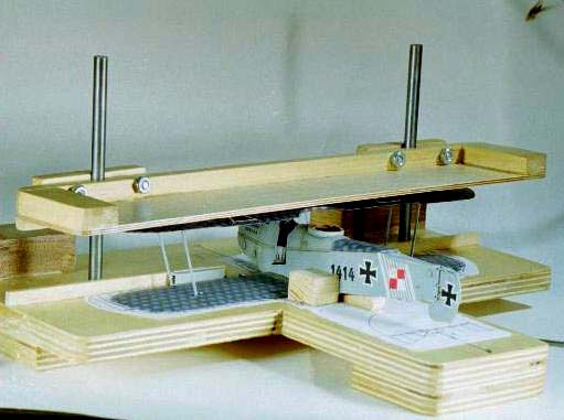 Because
I have finally learned to plan assembly of the major components before
detailing and painting, I set up my jig for the upper wing attachment
(an adjustable fixture I use on all biplanes), and cut the cabane struts
to size from brass Strutz stock. Since the plane was jigged up, I proceeded
to attach the top wing using white glue. This trial run was worth the
effort, since it revealed that the aft strut locating holes on the lower
wing were about 1 mm too far forward, and would have resulted in an inaccurate
strut configuration if not corrected. I built a second jig to assist in
attaching the floats. Eyeing the white metal struts with distrust, I replaced
the interplane and fuselage-float struts with brass; this is a heavy model.
Because
I have finally learned to plan assembly of the major components before
detailing and painting, I set up my jig for the upper wing attachment
(an adjustable fixture I use on all biplanes), and cut the cabane struts
to size from brass Strutz stock. Since the plane was jigged up, I proceeded
to attach the top wing using white glue. This trial run was worth the
effort, since it revealed that the aft strut locating holes on the lower
wing were about 1 mm too far forward, and would have resulted in an inaccurate
strut configuration if not corrected. I built a second jig to assist in
attaching the floats. Eyeing the white metal struts with distrust, I replaced
the interplane and fuselage-float struts with brass; this is a heavy model.
Assured that I would not encounter any traumatic surprises toward the end of the project, I disassembled and cleaned the components to begin the detail steps. I should have considered the center of gravity, which is too far aft on the model, and as a result the finished plane doesn't 'sit' properly. I compensated for this by pinning it to a base with small screws, but I would have much preferred to weight the nose or, better, the floats so it would sit correctly without artifice.
 I
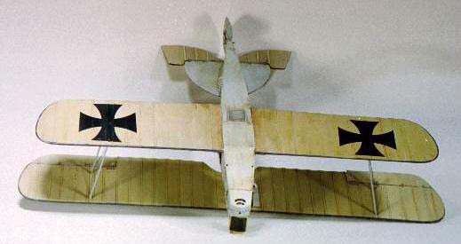
sanded the wings vigorously to achieve a thin section, and supplied rib
tapes for the bottom sides with .005 plastic strips. In retrospect, the
depiction on the resin wings was probably a better representation of balooned
fabric than the plastic I supplied, and in all events tapes are best provided
with decal strips. I cut and repositioned the ailerons, and prepared locating
points for the wing-mounted compass and anemometer. Thanks to the kit's
excellent Martin Digmayer plans, I confirmed the aileron control arrangement
and predrilled for these wires, as well as the minimal incidence wires
between the interplane struts.
I
sanded the wings vigorously to achieve a thin section, and supplied rib
tapes for the bottom sides with .005 plastic strips. In retrospect, the
depiction on the resin wings was probably a better representation of balooned
fabric than the plastic I supplied, and in all events tapes are best provided
with decal strips. I cut and repositioned the ailerons, and prepared locating
points for the wing-mounted compass and anemometer. Thanks to the kit's
excellent Martin Digmayer plans, I confirmed the aileron control arrangement
and predrilled for these wires, as well as the minimal incidence wires
between the interplane struts.
I made a new elevator from two pieces of .010 plastic to achieve a thinner component than the kit-supplied white metal version, and generally refined the elevator/stabilizer and rudder/fuselage joints and the prominent hinges.
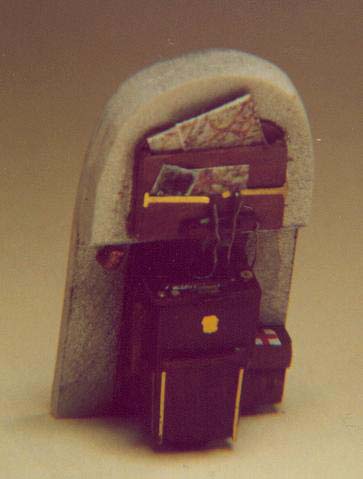
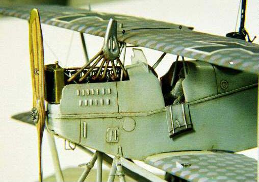
 Detail
components for the interior were fabricated from the kit-supplied photoetch
as well as from scratch; bear in mind that the pilot's cockpit is virtually
invisible, even if one opts to open the doors for a better look. The fuselage
internal structure was interpolated from that employed on the Brandenburg
W.33. The pilot's station of the W.12 is reasonably well documented from
a photo, and so supplying throttle, control wheel, hand pump, and dashboard
is easy enough. The pilotís seat atop the main gas tank, along with the
pedal and floor layout, is again derived from the documentation on the
W.33.
Detail
components for the interior were fabricated from the kit-supplied photoetch
as well as from scratch; bear in mind that the pilot's cockpit is virtually
invisible, even if one opts to open the doors for a better look. The fuselage
internal structure was interpolated from that employed on the Brandenburg
W.33. The pilot's station of the W.12 is reasonably well documented from
a photo, and so supplying throttle, control wheel, hand pump, and dashboard
is easy enough. The pilotís seat atop the main gas tank, along with the
pedal and floor layout, is again derived from the documentation on the
W.33.
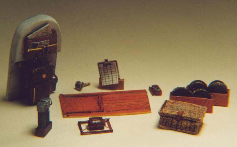 Filling
the gunner's station took a little more imagination, as the sole provided
fixture was an atypical seat. Consulting numerous photos of other German
two-seaters, I built a floor, and added a secondary floor-mounted compass.
I included a between-the-cockpits fuel tank (though I suspect that this
was a gravity tank unique to monoplane Brandenburgs), and added a map
case on the observer's side. I filled the case with maps, and stuck a
1/48 family snap-shot under the brass hold-downs. Several pencils were
provided for note-taking, as was a clipboard with a sheaf of forms. A
large hand-held camera was positioned over the sliding door in the floor,
as this seemed to be a logical stowage spot that could be used to take
pictures without removing the camera.
Filling
the gunner's station took a little more imagination, as the sole provided
fixture was an atypical seat. Consulting numerous photos of other German
two-seaters, I built a floor, and added a secondary floor-mounted compass.
I included a between-the-cockpits fuel tank (though I suspect that this
was a gravity tank unique to monoplane Brandenburgs), and added a map
case on the observer's side. I filled the case with maps, and stuck a
1/48 family snap-shot under the brass hold-downs. Several pencils were
provided for note-taking, as was a clipboard with a sheaf of forms. A
large hand-held camera was positioned over the sliding door in the floor,
as this seemed to be a logical stowage spot that could be used to take
pictures without removing the camera.
 I
added a small first-aid kit and a wicker basket for homing pigeons. A
pair of vacuum flasks went in for those long over-sea flights, as well
as a barograph and a couple of small instruments for weather observation.
A small folding seat was installed, and a safety harness attached to the
gun ring – my documentation revealed seaplane crews didn't buckle
in for take-offs and landings, preferring a hasty exit to being trapped
in a sinking craft. Finally, extra ammunition drums for the Parabellum
LMG 14 machine gun were stowed aft.
I
added a small first-aid kit and a wicker basket for homing pigeons. A
pair of vacuum flasks went in for those long over-sea flights, as well
as a barograph and a couple of small instruments for weather observation.
A small folding seat was installed, and a safety harness attached to the
gun ring – my documentation revealed seaplane crews didn't buckle
in for take-offs and landings, preferring a hasty exit to being trapped
in a sinking craft. Finally, extra ammunition drums for the Parabellum
LMG 14 machine gun were stowed aft.
All of these many small bit were concocted of plastic rod, tube and sheet; wire; brass shim, rod and tube, and photoetched parts; the pigeon coop and ammo spools were cast in resin from scratchbuilt plastic originals. I had originally begun to weave the wicker pigeon coop from brass wire, but the realization that it would be invisible under the gunner's seat brought me back to sanity.
 |
|
 |
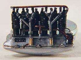 |
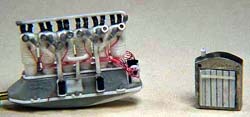
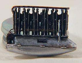
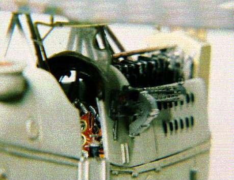
The kit supplies a Mercedes D.III engine, which is very different from the Benz I required. I deemed it more expedient to start from scratch than convert the one provided, and accordingly turned a brass cylinder using a Dremel tool as a lathe. From this were cast six resin cylinders which were attached to a suitable crankcase; the crankcase is not accurate, but it is invisible below the engine bearers anyway. The salient features of the Benz Bz.III are the twelve starboard pushrods, simply bent wire, and the rather elegant port induction tubes, which need a jig to properly cut and align the six different lengths of plastic rod. Once these basics are in place, magnetos, carburetors, pumps, bolts and the necessary wiring and plumbing are added as appropriate, recognizing that much of the engine is hidden in the cowl. The engine bearer/longeron deck, as well as the area between the cockpit and the engine, need additional detailing in the form of internal structure, control cables, plumbing and wiring, and gun mounting hardware/ammunition feeds for the pilot's synchronized weapon.
 I
had originally planned to incorporate working louvers into a vacuformed
engine cover. I had successfully created the necessary louver panels and
was getting through the tedious process of fairing these into the new
cowling and hiding the seams, but left the work under the heat of the
photo lamps too long, and melted it! Chastened and dismayed, with 30 hours
down the drain, I contented myself with correcting the louver configuration
on the kit-supplied part with plastic rod, and foregoing the pleasure
of being able to see through them.
I
had originally planned to incorporate working louvers into a vacuformed
engine cover. I had successfully created the necessary louver panels and
was getting through the tedious process of fairing these into the new
cowling and hiding the seams, but left the work under the heat of the
photo lamps too long, and melted it! Chastened and dismayed, with 30 hours
down the drain, I contented myself with correcting the louver configuration
on the kit-supplied part with plastic rod, and foregoing the pleasure
of being able to see through them.
Copper State provides excellent PE details for the fuselage and wing surfaces, and full advantage was taken of these. Be advised, though, that details varied on the production aircraft, and consult reference photos for the correct placement of what is provided as well as a guide for those items that need to be fabricated.
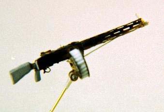 I
used Fotocut components to provide the details on the machine guns, along
with plastic card to provide the basic shape. Note that the Kriegsmarine
used the older IMG 08 version of the 'Spandau', and not the more commonly
encountered LMG 08/15 favored by the Army Air Service.
I
used Fotocut components to provide the details on the machine guns, along
with plastic card to provide the basic shape. Note that the Kriegsmarine
used the older IMG 08 version of the 'Spandau', and not the more commonly
encountered LMG 08/15 favored by the Army Air Service.
I spent a fair amount of time trying to convince myself - and anyone who would listen – that the German Navy's April, 1917 orders concerning the painting of aircraft meant that the hexes on these machines were painted, not printed fabric. I interpreted the absence of visible rib-tapes on the clearest photos as evidence supporting this thesis. The experts I consulted, however, were implacable in support of printed fabric, and so I opted to use the 'brown' scheme as supplied by Americal/Gryphon on their superb Kriegsmarine hex decal sheet as a compromise that would support either eventuality. While the painted and printed colors differed slightly as described in various resources, Americal's scheme, lightly oversprayed with gray, can stand in for either. Another reason to use Americal as opposed to the very attractive kit-supplied decals is that the size of the hexes is undeniably more correct; this is easily confirmed by counting hexagons on any photo where they are clear.
 Underside
fabric surfaces were finished in a suitable clear doped linen color concocted
from Floquil rail and military colors, and the side and underside grays
were mixed to match the Methuen references, again using Floquil products.
A trickier proposition was matching the decal hex colors, as the inevitable
touchups were required where the colors wrapped around edges and conformed
to the tops of the floats.
Underside
fabric surfaces were finished in a suitable clear doped linen color concocted
from Floquil rail and military colors, and the side and underside grays
were mixed to match the Methuen references, again using Floquil products.
A trickier proposition was matching the decal hex colors, as the inevitable
touchups were required where the colors wrapped around edges and conformed
to the tops of the floats.
I used PC Paintbrush to create the necessary aircraft stencils and the naval identity numbers that were to be applied to all components, and also the basis for Behrendt und Ruggebrecht propeller logos. These were prepared and printed in 1/12 scale, and shrunk to the correct size in photocopying the art onto decal paper.
 Once
the main components were painted, Futured, decaled, re-Futured, and oversprayed
with Polly-S flat, they were ready for weathering. While I am usually
very restrained in weathering WWI subjects, seaplanes require a slightly
heavier hand. This was accomplished with oils, applied in both heavy washes
and dry-brushed. Oil washes of black, browns, greens, and grays were wiped
off by rubbing a lint-free cloth in the direction of the airflow. Colored
pencils – both conventional and watercolor – were used to pick
out rib tapes and provide subtle streaking where lubricants or weather
would have stained the surfaces. Pastels were reserved until the entire
aircraft was assembled and would no longer need to be handled.
Once
the main components were painted, Futured, decaled, re-Futured, and oversprayed
with Polly-S flat, they were ready for weathering. While I am usually
very restrained in weathering WWI subjects, seaplanes require a slightly
heavier hand. This was accomplished with oils, applied in both heavy washes
and dry-brushed. Oil washes of black, browns, greens, and grays were wiped
off by rubbing a lint-free cloth in the direction of the airflow. Colored
pencils – both conventional and watercolor – were used to pick
out rib tapes and provide subtle streaking where lubricants or weather
would have stained the surfaces. Pastels were reserved until the entire
aircraft was assembled and would no longer need to be handled.
 Thanks
to the use of the jigs, the final assembly was relatively straightforward,
as previously cut and finished struts were slipped into position and attached
with epoxy. The thin resin wings remained pretty 'lively', and I wished,
too late, that I had provided monofilament incidence wires to help stiffen
up the structure. I compensated by replacing the remaining float struts
– and there are a lot of them – with bamboo. These replacements
provided more support, and photos revealed that the kit-supplied struts
were, if anything, a little undernourished. (Kit struts thinner than the
prototype? A modeling first!) Fitting the welter of struts was trickier
than I had supposed, as there are so many of them that it becomes difficult
to gain access to measure and install.
Thanks
to the use of the jigs, the final assembly was relatively straightforward,
as previously cut and finished struts were slipped into position and attached
with epoxy. The thin resin wings remained pretty 'lively', and I wished,
too late, that I had provided monofilament incidence wires to help stiffen
up the structure. I compensated by replacing the remaining float struts
– and there are a lot of them – with bamboo. These replacements
provided more support, and photos revealed that the kit-supplied struts
were, if anything, a little undernourished. (Kit struts thinner than the
prototype? A modeling first!) Fitting the welter of struts was trickier
than I had supposed, as there are so many of them that it becomes difficult
to gain access to measure and install.
 The
gun ring is too small, and needs replacement – and a few extra details,
which I supplied with plastic and brass. The final, fragile bits, including
the laminated and carved propeller, were slipped into place. I built beaching
gear, but their use would have created some tricky problems in attaching
the model to a base, so I left them as accessories.
The
gun ring is too small, and needs replacement – and a few extra details,
which I supplied with plastic and brass. The final, fragile bits, including
the laminated and carved propeller, were slipped into place. I built beaching
gear, but their use would have created some tricky problems in attaching
the model to a base, so I left them as accessories.
Conclusion
All told, I spent 340 hours during the six months of construction; longer than necessary, as I replaced a number of parts that were perfectly acceptable, provided a lot of ultimately-invisible details, and headed down some dead-ends, like my ill-fated louvers.
 Careful
planning is absolutely essential, as there are a number of potential pitfalls,
and resin wings of this span require reinforcement. All in all, Copper
State Models has provided a real gem, but it is not for tyros or the faint
of heart!
Careful
planning is absolutely essential, as there are a number of potential pitfalls,
and resin wings of this span require reinforcement. All in all, Copper
State Models has provided a real gem, but it is not for tyros or the faint
of heart!
References:
-
World War One Aero 124, 129, 131, 134
-
Cross and Cockade I/2, XI/1
-
Cross and Cockade International XIII/3
-
Over the Front IX/2
-
Scale Aircraft Modeler Int. 6/4
-
Scale Models April, 1983
-
Windsock Datafiles W.12, W.29

Addenda
 The
model was begun December 26, 1999, and completed June 12, 2000, with a
total of 340 hours invested, including the 27.5 hours lost in the ill-fated
louver experiment. These hours were committed as follows:
The
model was begun December 26, 1999, and completed June 12, 2000, with a
total of 340 hours invested, including the 27.5 hours lost in the ill-fated
louver experiment. These hours were committed as follows:
Research: 4.0 hours
Rough Shape: 7.0 hours
Cowl & Louvers: 32.5 hours
Wing Struts: 3.0 hours
Cockpits: 70.0 hours
Radiator and Engine: 53.0 hours
Machine Guns: 16.5 hours
Wing Setup: 6.5 hours
Wing Details: 21.5 hours
Fuselage Details: 14.0 hours
Empenage: 4.5 hours
Floats: 3.0 hours
Float Struts: 9.5 hours
Float Setup: 12.0 hours
Exterior Paint: 27.5 hours
Rigging: 2.5 hours
Beaching Gear : 4.0 hours
Final Assembly: 9.0 hours
Weathering: 13.5 hours
Propeller: 3.5 hours
Decals: 23.0 hours