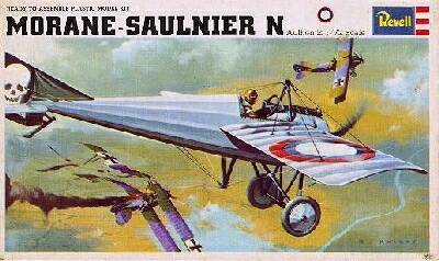
This project is based on Ray Rimell's article "Revell's Bullet" which appeared in Windsock Vol 2, Issue 1, and can also be found in "Best of Windsock" No.2. It is the correction of Revell's 1:72 scale Morane Saulnier N. In addition to Mr. Rimell's corrections, this article will deal with installing aftermarket landing gear by Roseparts and mention of all the lessons learned, (read that boo-boos made), in the process. I built the model straight out of the box as a kid in the ‘60s. I acquired a copy of the kit at a recent show and was about to enjoy another OOB build for old times sake when I was made aware of the considerable inaccuracies of this particular molding by Matt Bittner and Graham Nash of the WWI Modeling List. The challenge of major surgery on such a tiny model appealed to my warped sense of what makes modeling fun and I decided to "Rimellize" the Revell MoS Type N kit.
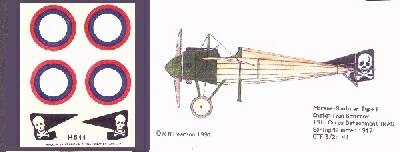
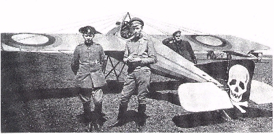
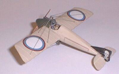
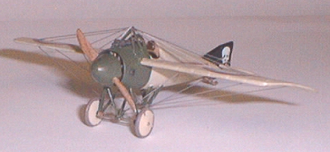
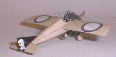
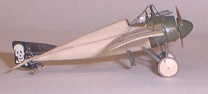
My kit is an older issue, the markings are for a Type I of the IRAS, detachment #19. This was the Russian outfit that used the black rudders with the white skull & cross bones painted on them. The moldings are done in white styrene that is of good quality and easy to work (fortunately in this case). There are 25 injection molded pieces, (excluding pilot & stand), decals and a two sided instruction sheet. I paid forty nine cents for the one I built as a kid and $5 for the one I recently purchased at a show. A tenfold increase in price over 30 years. I doubt I'll be alive, much less worth 10 times as much thirty years from now. Let me list the corrections needed to make this kit into an accurate model of this very interesting subject.
Ray Rimell's article " Revell's Bullet" from Windsock Vol.2 No.1 A good set of 1:72 scale drawings (Available in the MoS Datafile). Photos of the intended subject if available
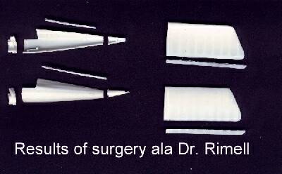
The first thing I did was to remove the parts from the sprues and clean them up. After that I performed the indicated surgery. The best "straight edge" for use on scoring the second stringer line on each fuselage half is a piece of the plastic tape that you feed those label makers where you turn the dial and punch the letter into the plastic. This stuff will stick down and makes an excellent non slip edge to scribe against. It comes up readily and doesn't leave a residue. It isn't any good on compound curves, but in this application it works like a champ. As far as I am concerned, there is only one scribing tool, the Bare Metal Foil panel line scriber. If you don't have one, do yourself a favor and get one. When I got to modifying the cockpit panel piece, I did it differently. First I glued the two fuselage halves together and removed the interior molding , thinning the cockpit walls with a burr on a battery powered dremel tool. Then I held the cockpit panel in position on the joined fuselage, the head rest stuck up almost 2 mm. I trimmed the tabs on the cockpit panel piece and then began wet sanding and fitting until I had removed enough plastic from the bottom edge so that the headrest sat even with the top of the modified fuselage. The cockpit panel piece is now the correct height but still too wide for the modified turtledeck. Fortunately the sanding done to reduce the height has exposed a much thicker mating edge. The overhang can be sanded off each side with a few strokes of a sanding stick working in the vertical plane. With the cockpit panel piece fitting correctly, I then began fitting the piece cut from between the wing panels earlier. After squaring up mating surfaces, I glued the center of the bottom of the piece to the joined fuselage halves. A drop of kicker and a few seconds to get a hard joint, then, one side at a time, gently pinch the side to match the mating fuselage side and CA it, then do the other side and shape up the seam. Now when you fit the cockpit panel piece over the rest of the fuselage, you will see it overhangs the front by a good 2 mm, Remove this and square up the edges. On the underside of the cockpit panel, there is a thick molding. Remove this with a burr so the cowl piece fits properly. Now take a long piece of sprue 3/16" in diameter and taper the end to fit closely into the hole in the very rear of the fuselage assembly. Cut 3/8" off the end and glue the plug in place with several drops of CA and kicker. The CA needs to fill the gap because the whole area will need to be reshaped by sanding. So now we have a 3 piece fuselage, (cowl, cockpit panel, and main body), These should fit together fairly well, but as Mr. Rimell points out, "...the butchered result will require filler in certain areas". That can wait. For now, use the burr to thin the inside walls of the cockpit area of the fuselage and the underside of the cockpit panel. Get these areas ready for details. When the cockpit area walls are thinned and ready to be detailed, the next step is to file and sand the rear of the fuselage to the correct shape. The top and bottom taper to an edge, the sides keep their present planform.
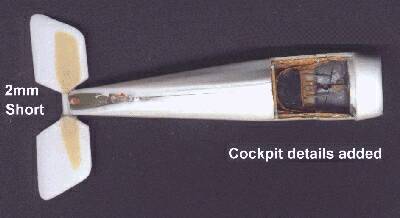
Mid stream in production I received a 1:72 scale drawing of a Type I. Just in casually holding the pieces in proximity to the drawing, something was obviously way wrong. The fuselage, now already assembled with some cockpit detail added, was 2mm too short. Oh, #$%^&*($%^&. A closer look, another read of Mr. Rimell's instructions and a measurement of the piece I'd amputated from the rear of the fuselage revealed I'd cut 2mm too much. Duh ah...Some days I just don't need to be around sharp instruments without adult supervision. Two pieces of card laid along the top & bottom of the fuselage and meeting 2mm farther back were CA'ed and sanded till it all feathered in smooth. A fortunately easy fix for a dumb mistake, unfortunately the first of several. Read on.
The detailing of the Revell MoS cockpit is pretty much up to the individual modeler. The kit seat is wrong, but could be cut down to a reasonable approximation of what the drawings show. I messed mine up and had to scratch build one. I began the interior detailing by painting the inside CDL and Aluminum where appropriate. Next I laid in stringers made of basswood (Midwest Micro Cut Scale Lumber .0208 sq.), followed by the diagonal frame members shown on the drawings. A Tom's Modelworks PE brass rudder bar and a joystick from stretched sprue for controls with hair fine stretched sprue control and bracing wires. This completed the detailing of the main cockpit opening in the fuselage. There are a couple of gauges and other odd details to go on the underside of the cockpit panel piece.
This is the hardest part of the entire project. I detailed the cockpit panel piece with the windscreen, Vickers gun, (Tom's Modelworks), Gun braces and instruments. I attached it to the fuselage at the apex of the turtledeck with a tiny drop of CA. Then I positioned the center of the front on the cowl with a nother tiny drop of CA. When the CA had set well, I pinched each side in as much as possible and CA then one at a time. Finally I filled the gaps with bits of strip and CA. It all is sanded smooth when done. This is tricky and requires concentration not to ruin the details. Done right, the wing attaches to the exact spot where all the fill goes and it will not be very noticable. Patience and persistence are the keys, though creative verbage seems to help at this point also.
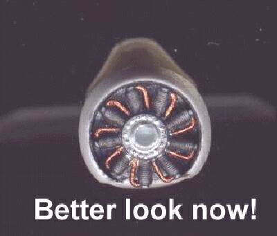
The Revell kit engine is a little jewel. It cleaned up well and I painted the cylinders Metalizer Burnt Metal, the case, Metalizer Steel, the intakes Copper and the pushrods molded on the back of the cylinders Silver.
The kit propeller is correct for the Type I except for the bullet deflectors. I just removed them and finished the prop in Testors' Wood drybrushed with Rust for texture.
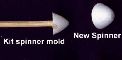
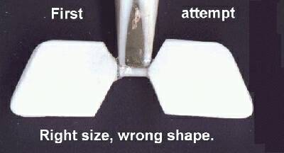
The kit spinner is too small and too pointy, Mr. Rimell recommends tossing it, but I didn't. I saved it to use as a mold to form a better one. I CAed a toothpick into the back of the kit spinner for a handle. Then I took a piece of 20 thou card about an inch and a quarter square, held in tweezers , and heated it over the flame of a tea candle. Heat both sides until the piece of card just starts to deform. To support the heated card while I pushed the kit spinner into it, I used an upturned red plastic cap from a tube of #11 blades. Anything with a circular opening a bit larger in diameter than the spinner will do. Once molded, the new spinner is the correct size, but still too pointy. Put a few drops of CA into the back side of the cone. Do this a couple of times to build up some solid CA in the point. Be careful not to put too much CA or kicker in at once or it will heat up and melt the cone. When the CA has set, work the pointy end of the spinner to the correct shape referring to your reference photos.
After slicing off the trailing edge of each wing panel, sanding the TE to a razor's edge, put a tiny drop of CA in each of the rigging dimples and sand these smooth. If you are doing this model as the MoS Type I rather than the MoS Type N, you need to scallop the trailing edge to represent the Type I's wire trailing edge. Now you need to bevel the wing panel root edges to match the fuselage sides. Remember, the whole point of separating the wing panels in the first place was to relocate them in the correct place just below the cockpit edge. Refer to drawings & photos for exact positioning. Make sure the wing panels are square & true when fitted up to the fuselage sides.
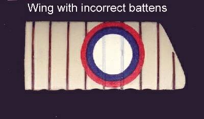
I was looking forward to doing the external rib battens which were a feature of Morane Saulniers. .After carefully painting both sides in my base shade of CDL, I laid strips of brown painted evergreen strip along each rib station, top & bottom. Some of this pre-painted strip didn't get pre painted, so it required a major effort to touch up ‘in-situ". This feat accomplished, I just had to see what the decals would look like and applied them.. They even settled down nicely over the battens. No sooner were they fully dry, than Matt Bittner finds evidence that Type I machines did not use the rib battens, but were done with regular rib tapes. Arrughhh !@#$%^&. Out with the dremel and sanding sticks and good bye battens & kit decals. I ended up doing the panels as described below and am quite pleased with the result if not the route taken to arrive at it.
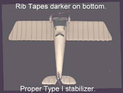
I painted and finished my wing panels before attaching them. My 1:72 rib taping method is to paint the top lighter than the CDL and the botom side darker than the CDL. When dry, I cut thin strips of masking tape and mask the rib stations. After masking the ribs, I spray the whole panel the CDL shade I am using. When the paint dries and the tape is removed the wing had lighter rib tapes on top and darker on the bottom. This is fairly quick, and very easy to do. The results are most effective.
Based on the photo of Smirnoff's machine, I faired in the windscreen frame piece to the cockpit panel piece using Glueit, a thick and fast drying alaphatic resin glue. This took several coats. When I was satisfied, I carefully trimmed away some of the chunkiness of the windscreen frame with a sharp blade. I had to file a groove for the Vickers gun that extended partly onto the front cowl piece.
I made a new fin, rudder and stab the correct size out of scrap card. As a result of lengthening the fuselage, I had to remove the enlarged stab I had originally made. Taking advantage of the opportunity, I made a better one to the outline on the I Type drawings. The stab ended up in two pieces, so I joined them with a bit of thin wire CA'ed into a groove cut with a sharp #11 blade in each piece of the stab.

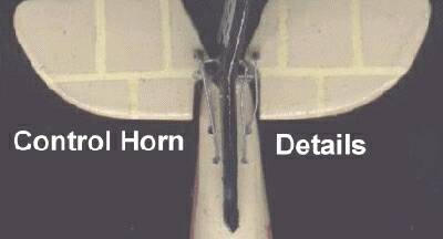
I scribed the line between the fin & rudder. I painted the stab to show rib taping like the wing. The fin & rudder I kept off the model and painted them black as a base for the Skull & cross bones decal. The control horns are from the Tom's PE sheet. 1:72 scale brass control horns were a major hassle until I discovered the following trick.: Using a very tiny drill dit in the #75 - #80 range, drill clear through the control surface at the correct location. Now when you cut the horn from the brass sheet, you will get a little burr at the attach point on the base of the horn, leave it there. The burr will fit into the little hole. A tiny drop of CA on the hole before you add the horn and the horn stays at right angles to the surface when you put it there. Best of all the hole goes straight through and the horn on the opposite side is lined up with the first one automatically.
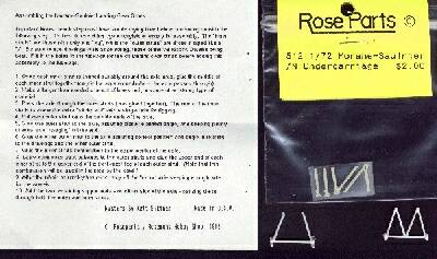
The kit LG is pretty bad and designed more to assemble easily than to look accurate, while I appreciated this feature when I first built the kit at age 12, nowadays I would rather have accurate than easy, (to a degree). Roseparts to the rescue! The Roseparts 1:72 MoS landing gear set is just the ticket here. The kit includes 2 Vee struts and the inner front struts. These parts are very thin precise resin castings that just look outstanding. They come in a bag and are easily removed and dressed. Best of all are the clear, detailed instructions which come with them.
The landing gear was another golden opportunity to cause myself trouble. The middle struts needed to be shortened. As I nipped a piece off, I just neglected to hold on to the long piece. It went orbital. I checked with Goddard Spaceflight Center to see if Hubble had picked up any images of it...they said they'd get back to me... A replacement whittled out of plastic strip is almost indistinguishable. The wire axle & sprue spreader bars were bound with very fine armature wire for bungees. I painted the bungees tan and gave them a wash in india ink. The kit wheels were almost 50% too small, so I used some resin ones from Roseparts. Here I learned about removing cast resin wheels from their castings. Cut around the join and sand the excess. Cut too close and you'll have a flat spot on the tyre. The model can rest on this and it will be invisible, but it is best to avoid the problem all together. Unfortunately, I learn slowly...the hard way.
For CDL, I started with Testors' light ivory and added a bit of gray and brown to get a grayish beige, but not too dark. For the green around the nose, cockpit & struts, I used Model Master Russian topside green.
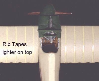
To do the rib tapes, I relied upon observations of CDL machines made at the Imperial War Museum by Sandy Adam. Mr. Adam reports that, viewed from above the doubled linen fabric of the rib tapes appears lighter and more linen colored than the surrounding single layer. When viewed from below, the effect is just the opposite. The double fabric of the tapes passing less light from above and appearing darker. The technique is described above. The whole model was given a coat of satin lacquer when finished.
I rigged the model with very fine stretched sprue. I pre-paint my sprue using Testors Metalizer Steel. Get a few drops worth in an upturned bottle cap. Take a Q-Tip that has been dipped in the paint and press the stretched sprue into the cap with the Q-Tip. Gently pull the sprue between the cap & Q-Tip. It will come out Steel colored and dries ready to use in seconds.
I expect I spent almost the same amount of time fixing mistakes as I did making them.....I mean building the model. All in all this project has taken just over 2 weeks and has been a graduate course learning from my own mistakes. All of Mr. Rimell's modifications worked very well. At first read, his article seems complicated, but it works out in styrene exactly as described and is actually quite easy to perform. If you want to use the Revell Morane Saulnier to make a Type N, Type I or Type V go right ahead, it isn't a hard conversion. If you like to detail cockpits, there are few WWI airplanes which have a more exposed one that is easier to see into than a Morane Saulnier.
 |
 |
 |
 |