
This article originally appeared in the May 1999 issue of Internet Modeler.
 Accurizing the
Testors Nieuport 17
Accurizing the
Testors Nieuport 17
An Introduction to WWI Modeling for the Average Plastic Modeler
By Steve Perry
Many modelers are put off by the complexity of two wings, exposed engines and rigging when they first take up modeling. Unfortunately that first impression remains long after their skill level makes such concerns irrelevant. The intent of this article is to provide some insight and guidance to modelers who would like to build their first WWI aircraft model.
OVERVIEW:
 The rest of
this piece will deal with the construction, detailing and finishing of
a Testors 1:48 scale Nieuport 17. This kit was chosen as a first WWI project
for several reasons. It is inexpensive, readily available, has a paint
scheme that can be done with either a hand or airbrush and incorporates
features, both good and bad, common to many WWI kits. Hopefully this article
will show you that there are no great challenges to WWI modeling that
cannot be amply met by the average modeler armed with a bit of know how.
The items specific to WWI modeling covered are: Correcting outlines, thinning
edges and struts, removing etched on markings, simulating wooden propellers,
detailing engines and guns and rigging the flying and control wires. While
there isn't the abundance of aftermarket details available for WWI models
that there is for subjects from that other dispute, adding details is
essential to raising both the enjoyment of the project and the quality
of the finished model. Both aftermarket and scratch built details are
covered. The article will take the project all the way from kit in box
to model on shelf, however skills and techniques common to plastic modeling
in general aren't dealt with in as great a detail as those more specific
to WWI modeling.
The rest of
this piece will deal with the construction, detailing and finishing of
a Testors 1:48 scale Nieuport 17. This kit was chosen as a first WWI project
for several reasons. It is inexpensive, readily available, has a paint
scheme that can be done with either a hand or airbrush and incorporates
features, both good and bad, common to many WWI kits. Hopefully this article
will show you that there are no great challenges to WWI modeling that
cannot be amply met by the average modeler armed with a bit of know how.
The items specific to WWI modeling covered are: Correcting outlines, thinning
edges and struts, removing etched on markings, simulating wooden propellers,
detailing engines and guns and rigging the flying and control wires. While
there isn't the abundance of aftermarket details available for WWI models
that there is for subjects from that other dispute, adding details is
essential to raising both the enjoyment of the project and the quality
of the finished model. Both aftermarket and scratch built details are
covered. The article will take the project all the way from kit in box
to model on shelf, however skills and techniques common to plastic modeling
in general aren't dealt with in as great a detail as those more specific
to WWI modeling.
THE KIT:
 The Testors
Nieuport 17 in 1:48 scale is the old Hawk mold that has been reissued
by Testors. It runs about $5 and is available in many local hobby shops.
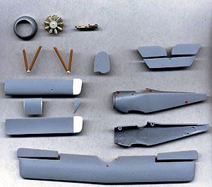
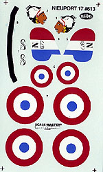
The kit comes with three sprues of gray plastic parts, decals and instructions.
It still has the roundels and other markings molded into the plastic,
more on removing these later.
The Testors
Nieuport 17 in 1:48 scale is the old Hawk mold that has been reissued
by Testors. It runs about $5 and is available in many local hobby shops.
The kit comes with three sprues of gray plastic parts, decals and instructions.
It still has the roundels and other markings molded into the plastic,
more on removing these later.
REFERENCE AND DOCUMENTATION:
Reference and documentary materials are essential to any scale model project. To those unfamiliar with WWI modeling it may seem that getting reliable documentation on subjects 80 years old could be a problem. Not so. The rest of the scale modeling community should be so lucky. Albatros Publications, Ltd publishes a series of booklets called Windsock Datafiles. These books are superb. They contain well-researched text, excellent, accurate drawings in 1:48 and 1:72 scales, a wealth of photos and color and marking guides. Each publication deals with a specific aircraft. Additional photos can be had in the Squadron Signal publications. One of the most frustrating aspects of modeling in general and WWI modeling in particular is waiting to build until you have gotten the proper documentation. Look at it as an investment that pays a handsome return. A list of references and documentation specific to the Nie.17 and where to obtain them is included at the end of this article.
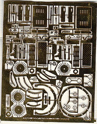
NECESSARY MATERIALS:
The following materials are needed to complete the project as described in this article: The Testors Nieuport Type 17C.1 1:48 scale injection molded plastic kit. Atlee 9 Cylinder LeRhone Rotary Engine 1:48 cast resin Tom's Modelworks British Gun Detailing Parts Photo Etched brass Vickers and Lewis guns 1:48 scale drawings of Nieuport 17C.1 (Windsock Datafile recommended)* Photo and text references (Windsock Datafile recommended) *Make copies of your drawings to use as working drawings on the building bench.
PARTS PREPARATION:
Before you can build or paint you need to give the parts some careful attention. Now is the time to correct problems with the shape or outline of parts, to clean up manufacturing defects like ejector pin marks and to remove those awful etched markings and hugely out of scale "details".
UPPER WING:
 The outline of
the Testors upper wing is not exactly a match to the drawings, but it
is close enough for our purposes and we'll leave the outline alone. Remove
all detail from upper and lower surfaces. The wing is better than average
as to scale thickness, but will still need to be thinned some. Work to
achieve to a finely tapered trailing edge. In the process of thinning
the wing, sand out the injector pin dents on the lower surface. Polish
out sanding scratches with progressively finer abrasives. Check the drawings
and drill/file slots for the aileron cranks in the correct locations.
Carefully remove the ailerons by means of a scriber, saw or X-acto blade.
Whichever the weapon, "careful" is the operative word. Dress the cut edges
on both wings and ailerons and round the aileron leading edges. The ailerons
can be set aside and primered, rib taped, and painted with the rest of
the wing and reattached in a deflected pose before decals are added.
The outline of
the Testors upper wing is not exactly a match to the drawings, but it
is close enough for our purposes and we'll leave the outline alone. Remove
all detail from upper and lower surfaces. The wing is better than average
as to scale thickness, but will still need to be thinned some. Work to
achieve to a finely tapered trailing edge. In the process of thinning
the wing, sand out the injector pin dents on the lower surface. Polish
out sanding scratches with progressively finer abrasives. Check the drawings
and drill/file slots for the aileron cranks in the correct locations.
Carefully remove the ailerons by means of a scriber, saw or X-acto blade.
Whichever the weapon, "careful" is the operative word. Dress the cut edges
on both wings and ailerons and round the aileron leading edges. The ailerons
can be set aside and primered, rib taped, and painted with the rest of
the wing and reattached in a deflected pose before decals are added.
LOWER WING:
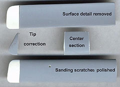 Remove all
detail from upper and lower surfaces. Sand away the injector pin dents
and remove the Hawk name engraved on the center section The tip of the
lower wing is incorrectly shaped. The degree of sweep is also incorrect.
Cleanly cut the right and left lower wing panels from the center piece,
(actually part of the fuselage). Save this piece. Using a sanding block,
adjust the taper of the wing panel roots to achieve the correct sweep
angle as shown on the drawings. Cut the angled wing tip off each panel.
Replace with an excess of plastic card, then trim, file and sand to the
correct shape. Use CA to bond and sand the joint 10 -15 minutes after
CA has set.
Remove all
detail from upper and lower surfaces. Sand away the injector pin dents
and remove the Hawk name engraved on the center section The tip of the
lower wing is incorrectly shaped. The degree of sweep is also incorrect.
Cleanly cut the right and left lower wing panels from the center piece,
(actually part of the fuselage). Save this piece. Using a sanding block,
adjust the taper of the wing panel roots to achieve the correct sweep
angle as shown on the drawings. Cut the angled wing tip off each panel.
Replace with an excess of plastic card, then trim, file and sand to the
correct shape. Use CA to bond and sand the joint 10 -15 minutes after
CA has set.
RIB TAPING:
Since all the surface detail has been sanded off the flying surfaces, better detail needs to be added. My method of doing this on 1:48 WWI aircraft is as follows:
Starting with the wing, (top, or bottom or either of the tailplanes), in a primered and sanded condition, carefully mark the rib and false rib locations in pencil. Now cut narrow strips of decal material (color doesn't matter here, but a contrast with the primer helps). As a rule of thumb, 3" wide tapes in 1:48 would be 1/16" wide. I tape the decal material to a flat hard surface, (glass), and cut with a new #11 blade and steel straight edge. Cut the strips slightly longer than the chord of the wing. For false ribs, cut the tapes exactly to length. Measure the exact length of the tape in from the edge of a sheet of paper and place a piece of masking tape with one edge exactly along the mark. Now slide the strip of decal material past the edge and butt it against the edge of the tape and cut the strip right on the edge of the paper.
I apply my rib tapes by painting a narrow strip of Future on the rib station and then applying the strip of decal material. Smooth, straighten, align and blot to your satisfaction and then dab on a bit more Future. Once dry, trim the tails off the strips with a sharp blade and press down with your fingernail any tape edges not already sealed and put a bit more future there. Once dry you are ready to paint.
FUSELAGE AND RUDDER:
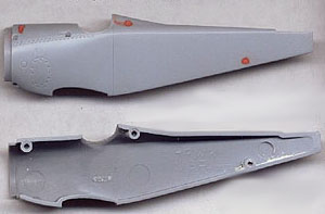 Remove the
rudder halves from both fuselage halves. Sand the detail off one rudder
and make it symmetrical in cross section. Discard the other one. You can
correct the outline a bit as per the drawings if you like. Sand off all
surface detail from the fuselage halves behind the cockpit. Leave the
inspection panel and lacing detail intact. Use putty to fill in mold dimples
on cowl, turtledeck and rear lower fuselage at locator pin positions.
The Hawk/Testors mold failed to catch the narrower bottom of the fuselage
characteristic of this aircraft. First cut off the tail skid and set it
aside. Now, wet sanding on a hard flat surface, and holding it at an angle,
sand the bottom of each half. Sand both halves equally, removing 1/32"
to 1/16" material from each half. Sand, fit, check against the drawings
with dividers, repeat, repeat.....until the correct shape is achieved.
Be sure to sand both sides equally, count the strokes. The fuselage bottom
is about 1/8" narrower than the top at the cockpit. The difference is
down to about 1/16" narrower at cowl line and stabilizer leading edge.
The "hump" inside the fuselage needs to be removed. Cut the center section
removed earlier from the lower wing panels exactly in half. Install one
half in each fuselage side. Sand and file to remove the hump.
Remove the
rudder halves from both fuselage halves. Sand the detail off one rudder
and make it symmetrical in cross section. Discard the other one. You can
correct the outline a bit as per the drawings if you like. Sand off all
surface detail from the fuselage halves behind the cockpit. Leave the
inspection panel and lacing detail intact. Use putty to fill in mold dimples
on cowl, turtledeck and rear lower fuselage at locator pin positions.
The Hawk/Testors mold failed to catch the narrower bottom of the fuselage
characteristic of this aircraft. First cut off the tail skid and set it
aside. Now, wet sanding on a hard flat surface, and holding it at an angle,
sand the bottom of each half. Sand both halves equally, removing 1/32"
to 1/16" material from each half. Sand, fit, check against the drawings
with dividers, repeat, repeat.....until the correct shape is achieved.
Be sure to sand both sides equally, count the strokes. The fuselage bottom
is about 1/8" narrower than the top at the cockpit. The difference is
down to about 1/16" narrower at cowl line and stabilizer leading edge.
The "hump" inside the fuselage needs to be removed. Cut the center section
removed earlier from the lower wing panels exactly in half. Install one
half in each fuselage side. Sand and file to remove the hump.
ELEVATOR AND STABILIZER:
Remove all detail from both sides, thin trailing edge, but leave the hinge line visible. You can sand the edges a bit to match the drawings or just leave it be. From the drawings drill and file the slots for the elevator control cable in the proper locations. Primer and rib tape as per earlier directions.
COWLING:
The cowling is extremely thick and the molded in engine needs to go. Be careful to preserve the roundness of the opening in the process of removing the attached cylinders. Use a dremel tool with a burr to thin down the inside of the cowl. Be sure not to thin the rear edge where it attaches to the fuselage, or it will no longer fit. Scribe panel lines and open up the access port on the bottom side. Refer to drawings for exact size and location.
COCKPIT DETAILS:
 Now that
you've spent several hours working on your Nieuport, it's time to actually
build some of it. Open cockpit aircraft were the general rule in 1914
- 1918 and highly detailed open cockpits are a hallmark of WWI models.
This sort of interior detailing needs to be completed before assembly
of the fuselage.
Now that
you've spent several hours working on your Nieuport, it's time to actually
build some of it. Open cockpit aircraft were the general rule in 1914
- 1918 and highly detailed open cockpits are a hallmark of WWI models.
This sort of interior detailing needs to be completed before assembly
of the fuselage.
The Testors kit has a molded pilot and a slab of plastic to glue across the cockpit for him to sit on. Cleaning up and painting the pilot will pretty well fill the cockpit hole with detail and may suffice for your tastes. If so, there is nothing wrong about a model with a nice pilot sitting at the controls.
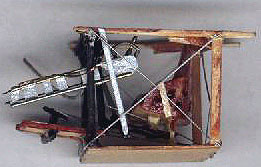
However, since one of the attractive features of WWI modeling is the open cockpit, here is your opportunity to go for the Oohs and Ahas. Brass cockpit sets are available for the Nie.17, but I built my cockpit completely from bits and pieces of wood and card lying about my modeling bench.
I started with a piece of 1/64" plywood as the floorboard. Using a pair of dividers, I established the basic dimensions. Test fitting and a sanding stick established the final size and shape. Using photos of a stripped down Nie.17, I built up a cockpit "tub" consisting of a seat, structure and bracing cables, controls and instruments.
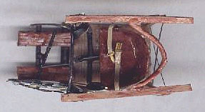 Fit and
fiddle is the watchword here. I began with the floor as described. Next
went the upright structural members. The back two out of wood strips and
the front two out of styrene rod. The piece of the longeron connecting
them was added next. A seat made from 1/64" ply was added. (Soak the back
piece in hot water before attempting to glue it to the curved seat bottom).
Flight controls were made from bits of rod, brass and plastic. Heel boards
for the rudder bar were made out of coffee stirrer sticks. Bracing and
control cables were from stretched sprue. I used Foto-Cut brass instrument
beezels for the front of the two gauges with a section of sliced sprue
for the instrument body. Re-Heat brass buckles were used on the seatbelt.
While the result is not 100% accurate, it looks great and once installed
in the fuselage it gives the model a recognizable Nieuport cockpit. If
scratch building a cockpit challenges you, go for it. Give it a try, the
worst thing you can do is waste a few pennies worth of material and some
time. You will probably end up proud of your effort and glad you made
it.
Fit and
fiddle is the watchword here. I began with the floor as described. Next
went the upright structural members. The back two out of wood strips and
the front two out of styrene rod. The piece of the longeron connecting
them was added next. A seat made from 1/64" ply was added. (Soak the back
piece in hot water before attempting to glue it to the curved seat bottom).
Flight controls were made from bits of rod, brass and plastic. Heel boards
for the rudder bar were made out of coffee stirrer sticks. Bracing and
control cables were from stretched sprue. I used Foto-Cut brass instrument
beezels for the front of the two gauges with a section of sliced sprue
for the instrument body. Re-Heat brass buckles were used on the seatbelt.
While the result is not 100% accurate, it looks great and once installed
in the fuselage it gives the model a recognizable Nieuport cockpit. If
scratch building a cockpit challenges you, go for it. Give it a try, the
worst thing you can do is waste a few pennies worth of material and some
time. You will probably end up proud of your effort and glad you made
it.
GUNS:
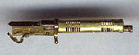 Nieuport
17's were equipped with both Vickers guns and Lewis guns depending on
the particular service of the aircraft you choose to model. The Tom's
Modelworks brass "British Guns" sheet has two of each plus two scarff
rings and is an excellent value. The particular aircraft I chose to model
was Italian and was equipped with a single Vickers gun synchronized to
fire through the propeller. There are 13 brass pieces provided on the
Tom's sheet, plus one bit of plastic you supply used to make up the Vickers
gun. As with all brass PE parts, work carefully, one piece at a time.
It looks harder than it is.
Nieuport
17's were equipped with both Vickers guns and Lewis guns depending on
the particular service of the aircraft you choose to model. The Tom's
Modelworks brass "British Guns" sheet has two of each plus two scarff
rings and is an excellent value. The particular aircraft I chose to model
was Italian and was equipped with a single Vickers gun synchronized to
fire through the propeller. There are 13 brass pieces provided on the
Tom's sheet, plus one bit of plastic you supply used to make up the Vickers
gun. As with all brass PE parts, work carefully, one piece at a time.
It looks harder than it is.
The Testors kit has a better than average injection molded Vickers gun and Lewis gun. If the brass gun kit is too much work for your tastes, clean up the kit pieces. These do well just painted nicely or you can add a few details like a hand strap for the Lewis gun magazine or an ammo belt and chute for the Vickers out of scrap card and bits. (I miss the old Comet models with a drawing of a complex detail and a note on the plans saying, "Carve from scrap balsa".)
WORKING WITH BRASS:
The 3 most important problems to solve when working with brass fiddly bits are:
1/ How to cut the parts loose without sending them twanging into oblivion.
2/ How to apply a sufficiently small drop of CA.
3/ How to pick up the pieces.
 First, you
"slice" the part off the fret. Place a piece of typing paper on a hard
surface. Place the fret on the paper and with a very sharp #11 blade,
position the blade exactly next to the edge of the part. The blade tip
is held against the attachment and pushed into the paper. Since the blade
is at an angle, it cuts the piece with a slicing action. This reduces
the tendency of the cut part to go orbital. To eliminate it entirely,
hold the fret firmly to the paper with your thumb and index finger. With
the free pointer finger, cover the blade tip and part being cut. As you
push the blade into the paper, you will hear/feel a "Tic" and the part
is cut. Lift up the fret carefully so as not to flick the part away.
First, you
"slice" the part off the fret. Place a piece of typing paper on a hard
surface. Place the fret on the paper and with a very sharp #11 blade,
position the blade exactly next to the edge of the part. The blade tip
is held against the attachment and pushed into the paper. Since the blade
is at an angle, it cuts the piece with a slicing action. This reduces
the tendency of the cut part to go orbital. To eliminate it entirely,
hold the fret firmly to the paper with your thumb and index finger. With
the free pointer finger, cover the blade tip and part being cut. As you
push the blade into the paper, you will hear/feel a "Tic" and the part
is cut. Lift up the fret carefully so as not to flick the part away.
Make up a set of "glue needles" Take sewing needles with eyes of varying size and nip off the ends making the eye into a two prong fork. Dip this in a puddle of ca and you can get just the size drop of CA you need. Make little handles out of wood to stick the sharp end into. The fork will clog with dried glue very quickly. Hold the fork in the flame of a lighter and in a couple of seconds the CA is gone. Keep a dish of water to dip it in and cool it before using again.
Finally you will need a good pair of pointed tweezers. These need to be precision made to a quality that enables you to pick up a flat piece of brass by the edges when it is lying flat on a hard surface. Do your self a favor and if you do not already use an Opti-visor, learn to . They are awkward at first, but they give you the ability to work on fine details.
FUSELAGE ASSEMBLY:
Now that you have a lovely interior constructed, its time to button that puppy up before you smash it. I attached the cockpit assembly to one side of the fuselage. Note that since you sanded the fuselage bottom edges to produce a taper, the bottom will not be flat. Take this into account when positioning the cockpit assembly. Make a former and headrest to fill the gap in the kit.
Join the fuselage halves with CA. Use CA to fill any gaps and wet sand the seams to invisibility. Do not worry about the bottom. Skin the entire bottom with 5 thou card to get a flat smooth surface.
STRUTS:
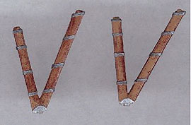 The mainplane
struts that come in the kit are the correct size and angle, but are much
too thick. These need to be sanded to about half their original thickness
and the edges tapered to give them an airfoil cross section. Metal attachment
fittings at the base of the vee can be simulated by properly shaped 5
thou card. The cabane struts in the model are half right. The front ones
are correct except for requiring thinning . The rear ones are all wrong.
The Nie.17 had an inverted vee shaped rear cabane strut which incorporated
the windscreen. Make this out of a triangle of clear, thin plastic with
Evergreen strip along the edges for the strut members. Paint the portion
that was wood on both sides. Be sure that the pins on the end of the mainplane
struts are trimmed so the strut will sit flat in the hole which is now
shallower since thinning the wing.
The mainplane
struts that come in the kit are the correct size and angle, but are much
too thick. These need to be sanded to about half their original thickness
and the edges tapered to give them an airfoil cross section. Metal attachment
fittings at the base of the vee can be simulated by properly shaped 5
thou card. The cabane struts in the model are half right. The front ones
are correct except for requiring thinning . The rear ones are all wrong.
The Nie.17 had an inverted vee shaped rear cabane strut which incorporated
the windscreen. Make this out of a triangle of clear, thin plastic with
Evergreen strip along the edges for the strut members. Paint the portion
that was wood on both sides. Be sure that the pins on the end of the mainplane
struts are trimmed so the strut will sit flat in the hole which is now
shallower since thinning the wing.
ASSEMBLY:
First add the lower wings. Tack to the fuselage at the correct sweep, dihedral and angle of incidence. Refer to your reference drawings. Once both wings are tacked to the correct position, CA them in place. Align and CA the horizontal stabilizer in place on the rear of the fuselage.
ENGINE:
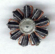
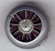 Whether you use an aftermarket engine of cast metal or resin or simply
add detail to what comes with the kit, now is the time to do it.
Whether you use an aftermarket engine of cast metal or resin or simply
add detail to what comes with the kit, now is the time to do it.
About all you can add to the kit engine is pushrods. These can be made from stretched sprue or brass wire. The Atlee cast resin engine allows for a bit more detail. Again add it out of stretched sprue or brass. I made mine out of 3 sized of brass wire and some very fine copper armature wire for the plug wires
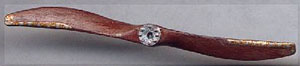 PROPELLER:
This kit has a decent prop that can look quite nice if cleaned up and painted. I added Foto-Cut brass prop bosses.
LANDING GEAR:
Whatever pains you take to correctly align the landing gear will be rewarded by not being noticed. Whatever pains you avoid will be hideously punished and harder to hide than the proverbial foreign matter in a punch bowl. Trimming and dry fitting to get it right is worth the effort. I didn't do too much to the LG. I made the characteristic plate at the vee out of 5 thou card, but only painted the notches on. I used thread wrapped around the axle to represent bungee chords.
RIGGING:
 You can rig a
WWI model with anything you want, but I have found that stretched sprue
gives me the best results. Mono filament sewing thread and very fine steel
wire is also used. I have had so much success with stretched sprue that
I have never experimented with the other rigging materials.
You can rig a
WWI model with anything you want, but I have found that stretched sprue
gives me the best results. Mono filament sewing thread and very fine steel
wire is also used. I have had so much success with stretched sprue that
I have never experimented with the other rigging materials.
Start with a piece of sprue between 1/8 and 3/16 inch in diameter and at least 2 inches long. I use a common tea candle for heat. I hold the sprue an inch or so above the flame and rotate it to heat it evenly. When you can bend it 30 degrees and still rotate it like a universal joint, it is ready.
Pull the ends evenly apart. If you've never done this before you will pull it slap in two. Keep trying, with practice you can learn to pull exactly the diameter you want.
When you have a piece you are happy with, it is time to paint it. I use Testors Metalizer Steel in the bottle. Shake the bottle well and lay the upturned cap on the bench. Now dip a Q-Tip in the paint and use it to hold the sprue to the inside of the upturned cap. Pull the length of the sprue between the cap and the Q-Tip. The sprue will come out painted and dries in seconds.
Now you have a piece of sprue ready to use. Look at it carefully. You will notice that it is probably too thick near the ends and way too thin in the middle. This leaves two portions of usable diameter. Cut out the too thin middle and the too thick ends and you will have two usable pieces. If the total length was 2 ft, you will end up with 2 pieces about 8 -10 inches long each.
 The actual rigging
isn't too hard. Each piece generally has a visible end and a hidden end
relative to looking at the model from a normal perspective. It is best
to attach the visible end first. I drill a # 75 or so hole where the wire
attaches. This hole can go all the way through on the fuselage, but is
better left as a socket on the wings. Dip the end of the sprue in a bit
of CA and carefully place the end with the tiny drop of glue into the
hole/socket you prepared. Let the thing set!. When dry, pull the spue
tight and mark where to cut the other end. This is the hidden end and
attaches with CA. Do not worry about slight slackness in the wire. Heat
a pin held in a wooden handle over a candle. When good and red, move it
quickly under the sprue. Move it around a bit under the sprue and suddenly
the sprue will magically tighten. Leave it still too long or hold it too
close and you will melt through the sprue. If this happens, just trim
off the sprue with a sharp blade and re-do it. You will do this a few
times, but you will also be surprised at how well it does work and how
quickly you learn not to melt the wire.
The actual rigging
isn't too hard. Each piece generally has a visible end and a hidden end
relative to looking at the model from a normal perspective. It is best
to attach the visible end first. I drill a # 75 or so hole where the wire
attaches. This hole can go all the way through on the fuselage, but is
better left as a socket on the wings. Dip the end of the sprue in a bit
of CA and carefully place the end with the tiny drop of glue into the
hole/socket you prepared. Let the thing set!. When dry, pull the spue
tight and mark where to cut the other end. This is the hidden end and
attaches with CA. Do not worry about slight slackness in the wire. Heat
a pin held in a wooden handle over a candle. When good and red, move it
quickly under the sprue. Move it around a bit under the sprue and suddenly
the sprue will magically tighten. Leave it still too long or hold it too
close and you will melt through the sprue. If this happens, just trim
off the sprue with a sharp blade and re-do it. You will do this a few
times, but you will also be surprised at how well it does work and how
quickly you learn not to melt the wire.
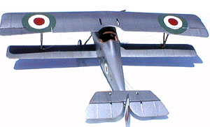
FINAL FINISH:
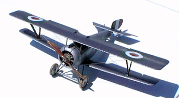
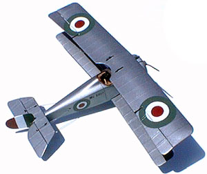
I painted my Nieuport with Pactra Acrylic Gunmetal as my references showed Macchi built Italian Nieuports had a darker silver dope finish. After decals have been applied, I coated the whole model with a satin lacquer, (Clearcoat with a bit of Dullcoat added)
RECOMMENDED SOURCES AND MATERIALS:
The single best resource for modeling WWI airplanes or anything else WWI related is The World War One Modeling List . This is an E-Mail list of modelers and historians who are only too happy to answer questions and help in researching WWI modeling projects. Check out their web page, the FAQ link on that page will take you to directions for subscribing to the list.
Windsock Datafiles by Albatros Publications
Flying Machine Press book French Aircraft of the First World War
Photos of the particular airframe you are modeling