
This article originally appeared in the May 1999 issue of Internet Modeler.
 Scratchbuilding
the Bristol F2b Fighter in 1/48 scale
Scratchbuilding
the Bristol F2b Fighter in 1/48 scale
by Shane Weier
THE AIRCRAFT:
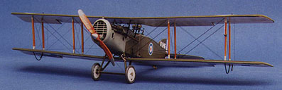
On the morning of 5 April, 1917 a new two seat fighter flew its first combat sorties in the dangerous skies over Douai on the Western Front. Victoria Cross winner, Captain W Leefe Robinson led a patrol of 48 Squadron Royal Flying Corp's brand new Bristol Fighter F.2A on an offensive patrol. But his tactics, learned to best protect earlier, less manoeuvrable two seaters were unsuccessful and his luck was worse.
At 11:00 the six Bristols met five Albatros fighters of the elite Jasta
11. By the time the surviving RFC aircraft made their escape, four had
been shot down, including 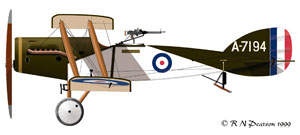 Leefe Robinson, two of them by Jasta 11 commander, Manfred von Richthofen.
Von Richthofen never held the Bristol Fighter in much regard, but when it was flown aggressively, as a fighter, with the pilot using his forward firing Vickers gun to attack while his observer protected his back, it became probably the most effective two seater of World War One. Many German pilots would rue the day in "Bloody April" that this tough, versatile and powerful aircraft was first introduced to the fray.
THE MODEL:
Seventy-eight years later, I too was in need of an exciting new aircraft to bring a bit of life to my modelling campaign. I was suffering richly deserved burnout from a previous over ambitious project, and wanted to model a subject which really appealed to me, yet provided enough challenge to be more than a shake the box project. For no better reason than that I liked the shape of the aircraft and had recently seen an inspiring (and genuine) WW1 colour photograph of one, I chose to build a Bristol F.2B, the improved version of Leefe Robinson's unsuccessful mount.
 At that time
there was no readily available kit of the Bristol F.2B in my preferred
1/48 scale, and no early prospect of one appearing. This suited me, as
it made my intention of building the model from scratch make a little
more sense than it might otherwise have done.
At that time
there was no readily available kit of the Bristol F.2B in my preferred
1/48 scale, and no early prospect of one appearing. This suited me, as
it made my intention of building the model from scratch make a little
more sense than it might otherwise have done.
Research proved to be difficult - I had the Squadron/Signal In Action volume, odds and ends of images in various magazines, but no decent plans and far too few detail photos. Having just discovered the Internet WW1 modelling list run by Allan Wright , I made my very first post asking if anyone could help me find decent references. Within two weeks I had plans, books, xeroxes and more advice than I could realistically use on just one project !
BUILDING A "BIFF":
In 1975 a book by Harry Woodman "Scale Model Aircraft in Plastic Card" was published in England. It was probably the first volume to thoroughly explore the use of sheet styrene in scratchbuilding, converting and otherwise improving model aircraft. My copy is dog eared and decrepit, but the techniques explained in it have stood the test so well that they are still repeatedly the subject of "How-To" articles in magazines like Fine Scale Modeler. The major airframe parts of this model were built using "Saint Harry's" simple and effective methods.
WINGS:
These were made by wrapping an embossed envelope of 10 thou plastic card around a balsa core. The plans were used to lay out the outline and rib stations for the entire span of each set of wings onto card. Each is drawn with both upper and lower surfaces depicted - drawn leading edge to leading edge. The card is then placed over a firm but slightly resilient surface - I used several sheets of light cardboard - and embossed by firmly drawing a tool along each rib position. I use an embossing tool of my own manufacture, but ballpoint pens, commercially available embossing tools and other items can be used to good effect.
A core is made of balsa, sanded to a fine cross section to allow for the card skin, and cut slightly less than the full chord of the wing to ensure a prototypically fine trailing edge. The card envelope is then folded along the leading edge, with the assistance of two small planks to ensure straightness and the heat from a stove element to allow a nice tight fold without splitting.
The core is then fitted inside the envelope to form the basic wing shape. A fuller explanation of how this is done can be found in one of the references at the end of this article.
FUSELAGE:
 Most of the
"Biff" fuselage is just a box, and making it from card proved simple enough.
The real aircraft structure is a wood frame with panels of doped fabric
laced at all four longerons over the rear fuselage, and with smaller side
panels laced over the cockpit area. These panels were represented using
5 thou card, very lightly embossed to barely suggest the structure underneath
and used to "skin" the basic box.
Most of the
"Biff" fuselage is just a box, and making it from card proved simple enough.
The real aircraft structure is a wood frame with panels of doped fabric
laced at all four longerons over the rear fuselage, and with smaller side
panels laced over the cockpit area. These panels were represented using
5 thou card, very lightly embossed to barely suggest the structure underneath
and used to "skin" the basic box.
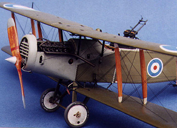
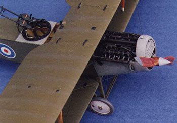
The cowling forward of the pilot was by far the most difficult area to capture effectively. It's a simple crash formed piece of card, but the contours in this area are not properly shown in most plans and proved difficult to make. I'm afraid that I'd never earn a living as a pattern maker, given that I made more than ten of them before I produced one both the correct size AND shape.
By contrast, the engine lower cowling was easy - just 3 patterns - but too deep to mould in one piece, so I was reduced to making halves and joining them. Given that the card was only 10 thou thick and needed to be butt joined I'd begun cursing the engine it was intended to display long before I'd properly hidden the seam.
ENGINE:
Scratchbuilding scale aero engines is frequently tedious but highly satisfying. Nothing quite catches the eye like an exposed and fully plumbed power plant, and while they invariably take time, the parts are rarely all that hard to make - but there are such a LOT of them. The Bristol F.2B has a V-12 motor, so aside from the engine block I needed 12 cylinders, 12 sets of valve gear, 24 springs, 2 carburettors, intake and exhaust manifolds, fuel lines, coolant lines, 24 spark plugs, 24 plug wires and so on and so forth.
 The engine
block was made by cutting a plastic card profile and two cross sections
at the engine bearer attachment points, then filling the armature these
created with Milliput - and carving away anything that didn't look like
a Rolls Royce Falcon engine. I'm far from dexterous, so the frequent mistakes
were rectified with more Milliput, and carved again, and again, and again
until I got it right. Flanges and mounts from plastic strip, and dozens
of bolt heads from shavings cut from a plastic rod shaped to hexagonal
completed the lower engine. I might just as well not bothered. It is almost
invisible to the human eye, there only for judges armed with proctoscopes
and God himself.
The engine
block was made by cutting a plastic card profile and two cross sections
at the engine bearer attachment points, then filling the armature these
created with Milliput - and carving away anything that didn't look like
a Rolls Royce Falcon engine. I'm far from dexterous, so the frequent mistakes
were rectified with more Milliput, and carved again, and again, and again
until I got it right. Flanges and mounts from plastic strip, and dozens
of bolt heads from shavings cut from a plastic rod shaped to hexagonal
completed the lower engine. I might just as well not bothered. It is almost
invisible to the human eye, there only for judges armed with proctoscopes
and God himself.
Cylinders and valve gear covers, exhausts and some piping were made from sections of plastic rod and strip, while the remaining piping is from copper, lead and aluminium wire. Magnetos, carburettors and other ancillaries were carved from plastic using scalpel, file, mini-drill, sandpaper or whatever suited the task at hand.
COCKPIT:
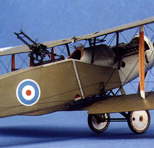
 Everyone
just has to look inside the cockpit of a model plane. The Biff has a large,
open and highly visible two place cockpit which needs every detail in
place to avoid that unfinished look. Mine was added after the box fuselage
was complete, but before the firewall, engine, and cockpit decking forward
of the pilot were added. This allowed me to make the side frames by pinning
plastic strip over drawings in the manner of a balsa flying model, add
the bracing wires, throttles, fuel pump, tailplane incidence lever, ammo
drums, seat supports, flare racks etc., and so on and only when the parts
were completed and painted, slip them into place from the front.
Everyone
just has to look inside the cockpit of a model plane. The Biff has a large,
open and highly visible two place cockpit which needs every detail in
place to avoid that unfinished look. Mine was added after the box fuselage
was complete, but before the firewall, engine, and cockpit decking forward
of the pilot were added. This allowed me to make the side frames by pinning
plastic strip over drawings in the manner of a balsa flying model, add
the bracing wires, throttles, fuel pump, tailplane incidence lever, ammo
drums, seat supports, flare racks etc., and so on and only when the parts
were completed and painted, slip them into place from the front.
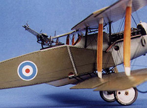
A fuel tank, observers foldaway seat, Vickers gun, ammo box and gun support bar, rudder bar and mounting, control columns and elevator and rudder cables were fabricated from brass, plastic rod and strip aluminium and added to the now almost completed cockpit. Last of all, one of the few commercial parts used - an etched brass seat back from Tom's Modelworks - was modified by adding a "roll" at the top and padded cushion and fitted on top of the fuel tank.
PAINTING AND DECALS:
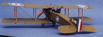
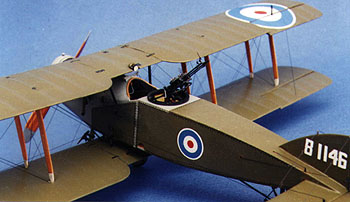 It's almost
always best to paint and decal a biplane before final assembly, and definitely
before adding rigging. Mine is painted in the standard PC.10 (khaki),
clear doped linen (CDL) and grey finish of late war RFC aircraft. Five
or six coats of paint and lots of masks were used to build up an impression
of the structure under the CDL surfaces while the upper surfaces were
shaded on ribs and edges.
It's almost
always best to paint and decal a biplane before final assembly, and definitely
before adding rigging. Mine is painted in the standard PC.10 (khaki),
clear doped linen (CDL) and grey finish of late war RFC aircraft. Five
or six coats of paint and lots of masks were used to build up an impression
of the structure under the CDL surfaces while the upper surfaces were
shaded on ribs and edges.
Cockades were made from disks of coloured decal sheet made by spraying appropriately mixed paints over clear sheet, and the tail number cut from white sheet after all too many attempts. The markings used represent B-1146, an aircraft of No.1 Sqn Australian Flying Corps, flown by Captain Ross Smith, the highest scoring ace in the Middle East theatre, and post war long distance aviator.
ASSEMBLY:
 The Biff
provides some unusual challenges, since the fuselage is suspended between
the wings rather than attached directly to either of them. I decided that
marrying up all the bits using any method other than a comprehensive set
of jigs would leave me with a nightmare task, so several weeks were expended
concocting interlocking supports capable of holding the parts in place
while allowing access for glue AND ensuring instant, precise and infallible
positioning. Ah well, that was the theory anyway. In the event, the fuselage
- engine - radiator- cowling assembly worked as predicted, but the attachment
of the lower wing almost gave me a coronary. Despite endless test fitting
in which the fuselage clipped onto the prepositioned struts with impressive
accuracy, the rotten thing absolutely refused to fit once the superglue
had been applied. Just at the point when the intrepid modeller had decided
to tear things apart and stamp off to the nearest hostelry for a restorative
ale - or ten - the model made a slight click, and the recalcitrant strut
popped into place.
The Biff
provides some unusual challenges, since the fuselage is suspended between
the wings rather than attached directly to either of them. I decided that
marrying up all the bits using any method other than a comprehensive set
of jigs would leave me with a nightmare task, so several weeks were expended
concocting interlocking supports capable of holding the parts in place
while allowing access for glue AND ensuring instant, precise and infallible
positioning. Ah well, that was the theory anyway. In the event, the fuselage
- engine - radiator- cowling assembly worked as predicted, but the attachment
of the lower wing almost gave me a coronary. Despite endless test fitting
in which the fuselage clipped onto the prepositioned struts with impressive
accuracy, the rotten thing absolutely refused to fit once the superglue
had been applied. Just at the point when the intrepid modeller had decided
to tear things apart and stamp off to the nearest hostelry for a restorative
ale - or ten - the model made a slight click, and the recalcitrant strut
popped into place.
Adding the top wing to a biplane is nerve racking enough when the lower wing is firmly attached to the fuselage. I have to report that this one was no easier than usual, but happily, no harder either. I frequently use bamboo to make "wooden" struts, and in this case a disposable chopstick provided the raw material. Brass pins set in each end eased accurate fitting of the struts. The "steel" struts on the model were all filed from brass rod.
With tail surfaces added, but without elevators, rudder and ailerons, I was ready to rig and detail the model.
DETAILS, DETAILS:
Here I include the undercarriage, added almost as an afterthought to the by now nearly completed model. Because the model is fairly heavy, the undercarriage struts were made rather like the real thing - from steel wire rod faired to airfoil shape. Bristol used wood for their fairings but I used 5 thou plastic card wrapped around the legs and glued. Then trimmed to shape. Axle and spreader bars are brass rod, superglued into place, though the axle itself is then further held in place with fine wire "bungee cord" wrappings.
 Other details
were formed from fuse wire, brass and plastic rod, aluminium sheet, blobs
of putty or glue or whatever practical or impractical idea came to mind.
It's impossible to explain this phase of modelling - everyone has their
own ideas of what works well, and one person will rarely be comfortable
with everything another uses. I have just two pieces of advice based on
the building of this model - keep an open mind and look at everything
you can think of which might solve the puzzle of how to create each piece,
and keep adding details until *you* stop enjoying doing it.
Other details
were formed from fuse wire, brass and plastic rod, aluminium sheet, blobs
of putty or glue or whatever practical or impractical idea came to mind.
It's impossible to explain this phase of modelling - everyone has their
own ideas of what works well, and one person will rarely be comfortable
with everything another uses. I have just two pieces of advice based on
the building of this model - keep an open mind and look at everything
you can think of which might solve the puzzle of how to create each piece,
and keep adding details until *you* stop enjoying doing it.
As usual, I rigged with black nylon monofilament "invisible mending thread" run completely through the wing surfaces and anchored with cyanoacrylate for strength. A little minor touch up of the paintwork is necessary but worth the extra strength of functional rigging.
FINAL TOUCHES:
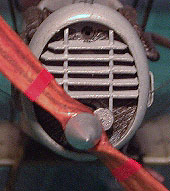
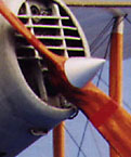 The photos
which provided the inspiration for this model showed two features I particularly
wanted to model - the impressively large wooden prop with its small aluminium
spinner, and the dual Lewis gun mounting.
The photos
which provided the inspiration for this model showed two features I particularly
wanted to model - the impressively large wooden prop with its small aluminium
spinner, and the dual Lewis gun mounting.
Carved wooden propellers are fairly simple to make. Laminate as many layers of veneer as are requires using *hard* woodworking glue. A scale drawing of the prop is glued to the front and the outline is carved away. The prop is then turned side on and the leading edges marked, followed by carefully cutting the blades to airfoil shape. The first one I made for this model came out beautifully, with fine edges and accurate blade cross section - but still looked somehow "odd". It wasn't until I was varnishing it prior to adding the decal stripes that I realised I had one blade angled for a clockwise turning prop - and the other for an anti-clockwise prop ! Ah what the heck - why should this be the only piece made at the first attempt.
The guns are a collection of simple shapes, but many of them are extremely fine. The Vane foresight is made of about 10 pieces and is just 2mm tall. Plastic strip, hypodermic tubing, fine brass and copper wire made the guns; plastic disks with wire knurling and wine bottle foil grips made the ammo panniers. Tom's Modelworks provided the four serrated quadrants and rear sight; these with the seat back and Aeroclub wheels bring to eight the total of commercial parts in a three and a half year project
CONCLUSION:
 There is
no "right" way to model. The only rule so far as I'm concerned is that
it should be fun. So - given that both Aeroclub and Blue Max released
kits before I had finished, was it worth the trouble? Did I have fun?
Hell YES. I think my model stacks up well against the professional product,
and even if it didn't, I enjoyed every moment I spent making it and value
every skill I learned and every minute I spent in the process. But most
of all, researching and discussing the model led me to friendships on
every continent except Antarctica - and who could ask for more than that.
There is
no "right" way to model. The only rule so far as I'm concerned is that
it should be fun. So - given that both Aeroclub and Blue Max released
kits before I had finished, was it worth the trouble? Did I have fun?
Hell YES. I think my model stacks up well against the professional product,
and even if it didn't, I enjoyed every moment I spent making it and value
every skill I learned and every minute I spent in the process. But most
of all, researching and discussing the model led me to friendships on
every continent except Antarctica - and who could ask for more than that.
REFERENCES:
Bristol Fighter, A Windsock Datafile Special Volume 1, J.M.Bruce; Albatros Publications Ltd.
Bristol Fighter, A Windsock Datafile Special Volume 2, J.M.Bruce; Albatros Publications Ltd.
Bristol Fighter, Windsock Datafile #4, J.M.Bruce; Albatros Publications Ltd.
Bristol Fighter In Action, Peter Cooksley, Squadron/Signal Publications
Men and Machines of the Australian Flying Corps 1914-19, Charles Schaedel; Kookaburra
Scale Model Aircraft in Plastic Card, Harry Woodman; Model and Allied Publications
Fine Scale Modeler, May and November 1995
Airfix Magazine, June,July, August 1986
Aircraft Modelworld, January 1987
Windsock Magazine, various issues, an invaluable source for WW1 fans