
This article originally appeared in the April 1999 issue of Internet Modeler.
 A Soviet
Sopwith
A Soviet
Sopwith
Toko's 1/72 Snipe
by Michael Kendix
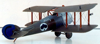
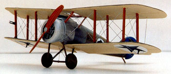
Lately, Toko has brought a number of 1/72nd scale World War One model kits to market. Reasonable in price, most can be purchased for less than $10; the Sopwith 7.F1 Snipe is among these, giving modelers an opportunity to build either a British World War One or Soviet early post-revolutionary period version. The Snipe legend was born on October 27 1918 when Major William Barker earned the Victoria Cross for shooting down four Fokker D.VIIs. Appearing in the First World War theater for the first time on September 23 1918, the Snipe was a late entrant into the war and continued to be used by the RAF until 1927. In that time, three Snipes were used by the Soviet Union during the early post-revolutionary period, when the nascent Soviet state was at war with Poland. On May 29 1920 Georgy Stepanovich Sapozhnikov of the Soviet Red Air Fleet was credited with shooting down Polish pilot Stefan Pawlikowski, an accomplishment that earned him the Order of the Red Banner. His colors are shown in the accompanying profile. A picture of his aeroplane can be found in Lennart Andersson's "Soviet Aircraft and Aviation 1917-1941"; the subject of this model.
THE KIT
I measured the kit's pieces against the 1/72nd scale
diagram from Windsock Datafile 46. The pieces are almost spot-on for the
"Late Model" version, with the possible 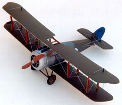 exception
that the tail-fin might be slightly undersized but the difference is exceedingly
small.
exception
that the tail-fin might be slightly undersized but the difference is exceedingly
small.
The kit looked good on the sprue with only a small amount of clean up necessary due to molding flash. The parts required hardly any sanding and smoothing; an easy job. The manufacturers provided two sets of decals but the British RAF roundels are hopeless; the inner red discs are tiny, almost dots, whilst the outer blue circles are too dark and too big. There is no room to use a stencil to correct the red "dots" because the blue outer rings are too wide. If you decide to make the RAF version, you should consider obtaining a new set of roundels and matching rudder decals.
PRECONSTRUCTION
Using a #80 drill bit, I drilled holes through the struts' ends, through which I intended to pull the rigging later in the assembly process. I also drilled the holes for the rigging in the fuselage, and the landing gear's fixed spreader and tail pieces. A king-post is not provided in the kit but you could add this feature; this would require further drilling for the associated rigging.
COLORS
 My
next task was to decide upon the color scheme and mix the paints. I recognize
that there are some paints provided on the market, which purport to replicate
Clear Doped Linen (CDL) and Protective Colouring Number 10 (PC-10), however,
there appears to have been some significant variation in shades, and no
consensus exists on the exact colors used, especially for PC-10. I find
it easier to mix the colors rather than search for the exact shade in
my local hobby stores or in mail order catalogues. Using the profile supplied
by Bob Pearson, I forged ahead. PC-10 was three parts Model Master's Dark
Earth and one part Floquil British Dark Green. The CDL was five parts
Model Master's Sand, 1 part Model Master's Insignia Yellow, and one part
Model Master's Dark Earth. The inside of the fuselage was painted PC-10,
and the cockpit interior was painted wood brown.
My
next task was to decide upon the color scheme and mix the paints. I recognize
that there are some paints provided on the market, which purport to replicate
Clear Doped Linen (CDL) and Protective Colouring Number 10 (PC-10), however,
there appears to have been some significant variation in shades, and no
consensus exists on the exact colors used, especially for PC-10. I find
it easier to mix the colors rather than search for the exact shade in
my local hobby stores or in mail order catalogues. Using the profile supplied
by Bob Pearson, I forged ahead. PC-10 was three parts Model Master's Dark
Earth and one part Floquil British Dark Green. The CDL was five parts
Model Master's Sand, 1 part Model Master's Insignia Yellow, and one part
Model Master's Dark Earth. The inside of the fuselage was painted PC-10,
and the cockpit interior was painted wood brown.
INSTRUMENT PANEL
One of the minor disappointments in this kit is that
the instrument panel does not 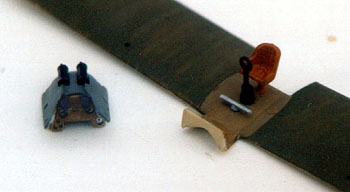 contain
the details depicted in the instruction sheet; it is totally flat and
contains no detail whatsoever. I decided to add detail by drilling holes
to simulate the instrument dials, copying the pattern of dials printed
on the instruction sheet. A #68 bit was used for the two lower left hand
side holes, a 72 bit for the left hand side dials above those, various
other slightly larger sizes for the other dials. I then cut some clear
thin .005 Evergreen sheet the same size and shape of the instrument panel,
painted it white, and attached it to the rear of the instrument panel.
The "white dials" showed through and I added a few details to the dials
using a 'Papermate' "Plastic Point", which gave the dials a slightly more
realistic appearance. These details were difficult to see when the fuselage
was closed, and when the top wing was in position, the panel was virtually
invisible without the proverbial "penlight and dental mirror".
contain
the details depicted in the instruction sheet; it is totally flat and
contains no detail whatsoever. I decided to add detail by drilling holes
to simulate the instrument dials, copying the pattern of dials printed
on the instruction sheet. A #68 bit was used for the two lower left hand
side holes, a 72 bit for the left hand side dials above those, various
other slightly larger sizes for the other dials. I then cut some clear
thin .005 Evergreen sheet the same size and shape of the instrument panel,
painted it white, and attached it to the rear of the instrument panel.
The "white dials" showed through and I added a few details to the dials
using a 'Papermate' "Plastic Point", which gave the dials a slightly more
realistic appearance. These details were difficult to see when the fuselage
was closed, and when the top wing was in position, the panel was virtually
invisible without the proverbial "penlight and dental mirror".
The front of the fuselage is not exactly as pictured
in the kit's diagram instructions since it leaves two small triangular
gaps. I was unable to ascertain whether this was 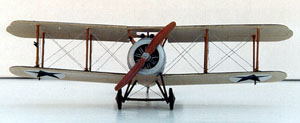 correct
or not. In any event, once assembled, this is not something that can be
seen without extremely close inspection; and it is fairly straightforward
to fill these spaces with thin card and putty. The fuselage sits on the
lower wing, with the cockpit seat and control stick mounted directly on
the lower wing piece. The seat was painted wood brown, the foot rudder
was painted aluminum and the control stick was painted black. After the
cockpit was completed, I joined the fuselage sides (the fuselage is split
vertically) and used 'Squadron White' for the lower and 'Squadron Green'
for the top cracks.
correct
or not. In any event, once assembled, this is not something that can be
seen without extremely close inspection; and it is fairly straightforward
to fill these spaces with thin card and putty. The fuselage sits on the
lower wing, with the cockpit seat and control stick mounted directly on
the lower wing piece. The seat was painted wood brown, the foot rudder
was painted aluminum and the control stick was painted black. After the
cockpit was completed, I joined the fuselage sides (the fuselage is split
vertically) and used 'Squadron White' for the lower and 'Squadron Green'
for the top cracks.
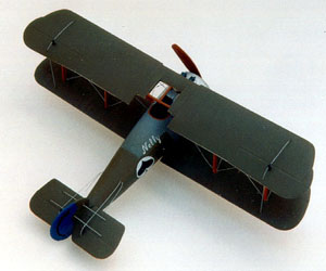
The cowl, and engine were then added. The engine was painted black and the "spokes" were painted aluminum. The cowl and front panels were painted aluminum and the mid panels painted British Ocean Grey, as shown in Bob Pearson's profile. The tail was painted blue using Humbrol 25. Gluing the fuselage together presented a challenge because the parts do not quite fit unless you do it perfectly first time. The front top piece containing the gun mounts is separate and this is problematic since it affords the opportunity of not getting the fuselage glued just right. On the other hand, it permits easy painting of the panelling; you don't need to mask it because it's separate.
ATTACHING THE WINGS
The next task was to attach the top wing; always one
of the more challenging tasks when building a biplane. This is especially
the case for this model since it is relatively 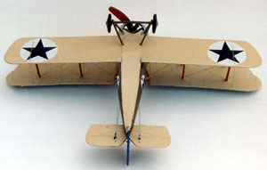 small
but contains four interplane struts on each side. The front and rear interplane
struts are not identical, so it was necessary to remember which struts
were associated with the front and back. Having glued the interplane struts
in place, and achieved the correct angle for these struts, I found the
forward cabane struts to be too short. This may have been due to a building
error on my part, however, replacing them using strips of Evergreen StripStyrene
was not too difficult, gradually shortening the strips until they fitted
into place. I then made the Venturi-form exhauster for the Badin petrol
system, which is situated on the starboard forward center-section strut.
This was not problematic; I used a small piece of .020 Evergreen styrene
rod. Ideally, this exhauster should look like two cones with their sharp
ends placed next to each other but given the small scale of this kit,
I passed on that particular level of detail. Regardless, it looks better
than the kit version since the kit makes the exhauster as part of the
strut, when in reality the exhauster is attached to the outside of the
strut.
small
but contains four interplane struts on each side. The front and rear interplane
struts are not identical, so it was necessary to remember which struts
were associated with the front and back. Having glued the interplane struts
in place, and achieved the correct angle for these struts, I found the
forward cabane struts to be too short. This may have been due to a building
error on my part, however, replacing them using strips of Evergreen StripStyrene
was not too difficult, gradually shortening the strips until they fitted
into place. I then made the Venturi-form exhauster for the Badin petrol
system, which is situated on the starboard forward center-section strut.
This was not problematic; I used a small piece of .020 Evergreen styrene
rod. Ideally, this exhauster should look like two cones with their sharp
ends placed next to each other but given the small scale of this kit,
I passed on that particular level of detail. Regardless, it looks better
than the kit version since the kit makes the exhauster as part of the
strut, when in reality the exhauster is attached to the outside of the
strut.
UNDERCARRIAGE
 Next
I assembled and attached the landing gear. This was straightforward but
I had to drill two new holes for the forward struts since they did not
reach exactly far enough forward to the extant holes. This is probably
a design fault in the model since there is no opportunity for me to have
affected this fit during construction. I was then faced with a choice;
either replace the landing gear struts or drill new holes for the landing
gear. I chose the latter since the distance was less than 2 millimeters
and I filled in the old gaps with Squadron White putty.
Next
I assembled and attached the landing gear. This was straightforward but
I had to drill two new holes for the forward struts since they did not
reach exactly far enough forward to the extant holes. This is probably
a design fault in the model since there is no opportunity for me to have
affected this fit during construction. I was then faced with a choice;
either replace the landing gear struts or drill new holes for the landing
gear. I chose the latter since the distance was less than 2 millimeters
and I filled in the old gaps with Squadron White putty.
DECALS - TAKE ONE
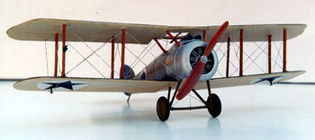
Prior to the rigging and attaching the aileron control horns, I painted the wings surfaces with Future enamel polish in preparation for the decals and to protect the model as I attached the rigging. The black five-point star decals were placed on the underside of the lower wing; there are no decals for the upper surface of the top wing. I used Model Master Decal Set on the surface of the wing, and then used Solvaset Decal Setting Solution on top of the decal to ensure a long lasting snug fit.
 RIGGING
I rigged the wings using "Invisible Thread". I then cut out the control horns for the tail and wing using Evergreen StripStyrene size .010 x .080", drilling through the paint before gluing the horns in place with CA glue. Adhering the control horns to the plastic, rather than the paint on top of the plastic, seems to provide a stronger bond. Using this method, I find the control horns do not detach as often when the rigging is tightened. The rest of the model was then rigged using the same "Invisible Thread".
DECALS - TAKE 2
The decals for the tail and the fuselage were then attached. The tail decals proved somewhat tricky due to their shape and the difficulty of positioning them on the rudder, but with a little patience, I was able to move them into position.
FINAL TOUCHES
A few touch ups and I was ready to spray on a couple
of coats of 'Model Master Lacquer Overcoat Lusterless (Flat)' from the
aerosol can. A semi-gloss version of this 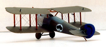 product
is also available for those who prefer the "newer look". Since I do not
possess an airbrush, the Lusterless Flat coating really helps provide
a nice surface to the model, and also helps to prevent the decals from
peeling off.
product
is also available for those who prefer the "newer look". Since I do not
possess an airbrush, the Lusterless Flat coating really helps provide
a nice surface to the model, and also helps to prevent the decals from
peeling off.
SUMMARY
In summary, this kit is a satisfying model to build. The parts fit together tolerably well, it is within the capacity of a relatively inexperienced modeler, and requires no aftermarket components to produce a realistic model of the original aeroplane. I recommend it.
THANKS TO:
Dave Vosburgh and Bob Pearson for both advice and references.
REFERENCES:
Windsock Datafile No.46: THE SOPWITH SNIPE by J M
Bruce
SOVIET AIRCRAFT AND AVIATION 1917-1941 by Lennart
Andersson
RED STAR SNIPES by Colin Owers; Windsock Magazine
Vol.10 No.4.