
This article originally appeared in the August 2000 issue of Internet Modeler.
 Blue
Max 1/48 Sopwith Snipe
Blue
Max 1/48 Sopwith Snipe
By Bucky Sheftall
Historical background
The design that ultimately became the Sopwith Snipe was created in response to an RFC request for a 'next generation' fighter forwarded to the British aircraft industry in the wake of the disastrous 'Bloody April' of 1917. RFC HQ's specs called for a scout capable of a top speed of 135mph at 15,000ft and the ability to climb from 10,000 to 20,000ft in less than 10 minutes. The urgency inherent in these military/industrial complex maneuvers gives some idea of just how rattled the RFC higher-ups (not to mention the pilots themselves) must have been by the experience of that nightmare spring, and just how desperate they were at that point for a machine 'with an edge', even with the superlative and combat-proven Camel already in their arsenal. While the Snipe never did quite live up to either Sir Thomas Sopwith's great expectations or the RFC's optimistic specs, it was nevertheless loved by most of the pilots who flew it, and it went on to make a decent accounting of itself upon deployment a year later in the brief autumn of combat duty it was able to squeeze in before the November Armistice.
A post-hostilities 'back to the old drawing board' session for the Snipe worked out some stability kinks in the design by tweaking the control surfaces, among other changes. The resultant aircraft turned out to be sturdy, if not blazingly fast, and considerably more forgiving to fly than its skittishly hyperactive and gyroscopically temperamental (if more dazzlingly maneuverable) older sibling the Camel.
 Looking
over the basic layout of the Snipe, it almost seems to be an attempt at
a hybrid of the best attributes of the Camel and the SPAD, aiming for
the rotary engine-powered, nimble center-of-gravity aerobatic performance
of the former and the rugged durability of the latter. Late-war design
trends on both sides of the conflict are also evident in its stubby, conical
fuselage, a feature notably shared with other designs such as the Morane-Saulnier
AI and the Siemens-Schuckert D.III that was most likely an attempt to
counteract the tail-heaviness for which aircraft of the era were notorious.
However, any resemblance with those technically advanced French and German
designs ended there; fundamentally speaking, the Snipe was a much more
conservative – even mundane - design. In a sense, it was the penultimate
'classic' WWI construction canvas/wood/wire 'stringbag' fighter –
the last of the line destined to close this chapter in military aircraft
design, opening the way for the more advanced monocoque-framed and metal-skinned
fighters of the future.
Looking
over the basic layout of the Snipe, it almost seems to be an attempt at
a hybrid of the best attributes of the Camel and the SPAD, aiming for
the rotary engine-powered, nimble center-of-gravity aerobatic performance
of the former and the rugged durability of the latter. Late-war design
trends on both sides of the conflict are also evident in its stubby, conical
fuselage, a feature notably shared with other designs such as the Morane-Saulnier
AI and the Siemens-Schuckert D.III that was most likely an attempt to
counteract the tail-heaviness for which aircraft of the era were notorious.
However, any resemblance with those technically advanced French and German
designs ended there; fundamentally speaking, the Snipe was a much more
conservative – even mundane - design. In a sense, it was the penultimate
'classic' WWI construction canvas/wood/wire 'stringbag' fighter –
the last of the line destined to close this chapter in military aircraft
design, opening the way for the more advanced monocoque-framed and metal-skinned
fighters of the future.
Emphasizing its premature obsolescence, the service record of the design shows that the British were already dumping the Snipe on Third World air forces en masse as unwanted surplus by mid-1920 (Bruce, 1994), less than two years after the aircraft's initial deployment. The only bright note to this somewhat melancholy denouement is that the last military Snipes were able to see out their service in the late Twenties 'scouting' the beaches of Rio de Janeiro with the Flotilha de Caca. Unfortunately, the bikini had not been invented yet.
Barker and E8102
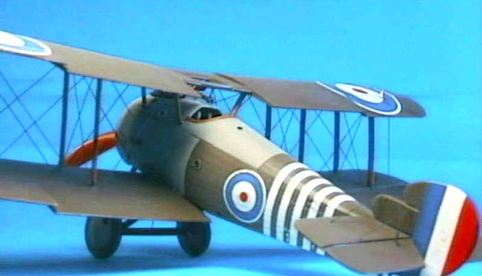
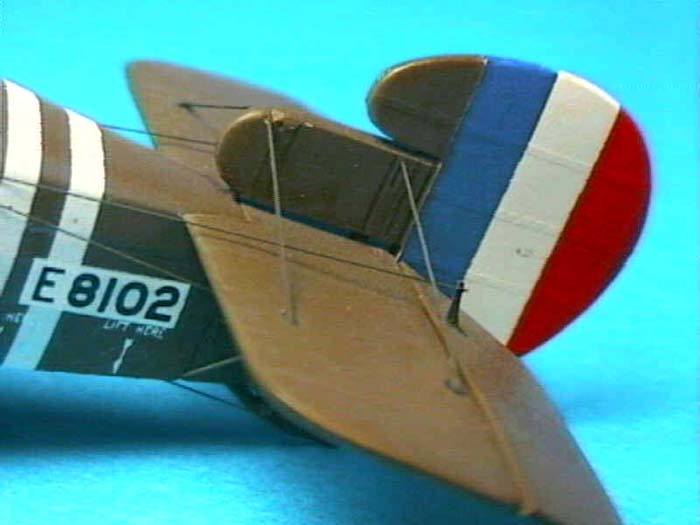
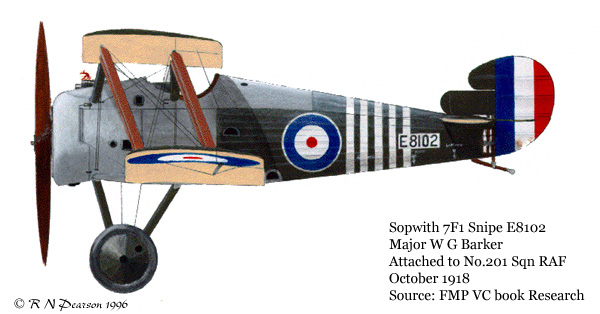 The
aircraft I chose to portray with this Blue Max kit is perhaps the most
famous Snipe of them all, 'E8102', which was piloted by Canadian Major
WG Barker in one of the most lopsided – and miraculous - aerial combats
of all time. On October 27, 1918, Major Barker found himself alone in
a fight to the death with no less than 15 Fokker DVIIs over German lines.
Wounded in both legs and an arm, Major Barker - in between fainting spells
from pain and blood loss and narrow pull-outs from nearly fatal out of
control 'death' spins - managed not only to down four of his foes in flames
but to nurse his crippled aircraft back to friendly lines and survive,
a feat of airmanship, courage and sheer fight-or-flight adrenaline rushes
that deservedly earned him the Victoria Cross.
The
aircraft I chose to portray with this Blue Max kit is perhaps the most
famous Snipe of them all, 'E8102', which was piloted by Canadian Major
WG Barker in one of the most lopsided – and miraculous - aerial combats
of all time. On October 27, 1918, Major Barker found himself alone in
a fight to the death with no less than 15 Fokker DVIIs over German lines.
Wounded in both legs and an arm, Major Barker - in between fainting spells
from pain and blood loss and narrow pull-outs from nearly fatal out of
control 'death' spins - managed not only to down four of his foes in flames
but to nurse his crippled aircraft back to friendly lines and survive,
a feat of airmanship, courage and sheer fight-or-flight adrenaline rushes
that deservedly earned him the Victoria Cross.
Major Barker's machine was an early production Snipe, with the 'cutaway' tail arrangement, small rudder and unbalanced ailerons characteristic of the type. The fuselage of this immortal aircraft is now enshrined in the Canadian War Museum.
Out of the box
 The
kit is another of Chris Gannon's well thought-out and executed creations
in the 1/48 Blue Max line. The wings of the kit feature the very tastefully
done rib-taping the series is well-known for, and on an even happier note,
it would appear that Blue Max has taken care of its infamous 'trailing
edge wing ripple' mold removal flaw, which is indeed happy news for all
of us who have had to sweat that problem out in the past with otherwise
excellent quality kits (the example of the Bristol Fighter springs immediately
to mind). Dimensions of the kit measure out accurately against Windsock
Datafile 46's 1/48 plans (to paraphrase the instruction sheet, it would
behoove you to "avail yourself" of this invaluable reference
– you'll need it to build the relatively instruction-free kit), and
important features of the aircraft all seem to be in the right positions
and in scale checked out against both plans and photos. One notably lacking
but quite salient feature (on the actual aircraft) is the main fabric
seam running along the fuselage and roughly parallel with the trailing
end of the plywood cockpit section, but this is easily scratch-rendered
with a little patient and careful panel-scribing and, if you're gung ho
enough, poncet-wheeling and crosshatch scratching for eyelets and lacing.
In retrospect, I could have used some of that dry-transfer stitching material
I've heard so much about on the WWI modeling BBSs and saved myself the
hassle. Well, live and learn, right?
The
kit is another of Chris Gannon's well thought-out and executed creations
in the 1/48 Blue Max line. The wings of the kit feature the very tastefully
done rib-taping the series is well-known for, and on an even happier note,
it would appear that Blue Max has taken care of its infamous 'trailing
edge wing ripple' mold removal flaw, which is indeed happy news for all
of us who have had to sweat that problem out in the past with otherwise
excellent quality kits (the example of the Bristol Fighter springs immediately
to mind). Dimensions of the kit measure out accurately against Windsock
Datafile 46's 1/48 plans (to paraphrase the instruction sheet, it would
behoove you to "avail yourself" of this invaluable reference
– you'll need it to build the relatively instruction-free kit), and
important features of the aircraft all seem to be in the right positions
and in scale checked out against both plans and photos. One notably lacking
but quite salient feature (on the actual aircraft) is the main fabric
seam running along the fuselage and roughly parallel with the trailing
end of the plywood cockpit section, but this is easily scratch-rendered
with a little patient and careful panel-scribing and, if you're gung ho
enough, poncet-wheeling and crosshatch scratching for eyelets and lacing.
In retrospect, I could have used some of that dry-transfer stitching material
I've heard so much about on the WWI modeling BBSs and saved myself the
hassle. Well, live and learn, right?
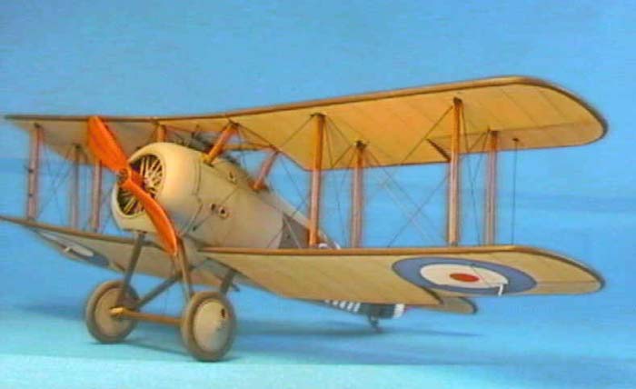
The kit provides the hobbyist with the option of building either Major Barker's Snipe or a version with a larger rudder and almost German-looking balanced ailerons representing an English proving ground aircraft that apparently never heard a shot fired in anger.
Decals are microthin, on register and pleasant to work with, and despite admonitions to the contrary, took to diluted decal solvent quite well. Other than the minor pucker factor of having to work 'under the clock' with the adhesive's rather quick setting time (ten seconds, perhaps, to position your decal properly before it is set for all eternity, a la Propagteam), the decals gave me no problems at all.
 As
with all simple-injection items, this kit could almost be deemed a 'virtual'
vac-form, as the amount of dry-fitting, grind'n'bumping and pure BST (blood,
sweat and tears) factor required to make everything go together properly
is more akin to the labor required of the vacuum kit genre than that of
injection plastic of the Tamiya/Hasegawa variety. Runner attachment points
are extremely thick, sometimes carrying over onto the actual piece (requiring
time-consuming 'cosmetic surgery' to correct), and there were numerous
injector pin marks which had to be dealt with, in my case mostly with
CA gap filling and precise rubber/silicate disc grinding.
As
with all simple-injection items, this kit could almost be deemed a 'virtual'
vac-form, as the amount of dry-fitting, grind'n'bumping and pure BST (blood,
sweat and tears) factor required to make everything go together properly
is more akin to the labor required of the vacuum kit genre than that of
injection plastic of the Tamiya/Hasegawa variety. Runner attachment points
are extremely thick, sometimes carrying over onto the actual piece (requiring
time-consuming 'cosmetic surgery' to correct), and there were numerous
injector pin marks which had to be dealt with, in my case mostly with
CA gap filling and precise rubber/silicate disc grinding.
Detail parts, including the undercarriage gear, cockpit frame and stringers, stick, rudders, seat and machine gun are white metal. The castings are of good quality, and were good-to-go with just a peremptory going-over with furniture finisher's steel wool. The only somewhat disappointing items in the metal parts pouch were the Vickers machine guns, which were just a little too grungy for my taste to use 'as is' and which I just didn't feel like bothering with trying to clean up (which might not have worked, anyway, despite my efforts). Instead, I bashed a pair of plastic Vickers guns from a DML Rickenbacker SPAD in the back of my 'stash' closet and they went in like a charm.
Interplane and cabane struts, as with all Blue Max products, are left up to the modeler to cut from 'Strutz' - like plastic strip provided in the kit. 'True strut length' guides are provided on the wedding invitation-sized instruction sheet. It's up to you to follow these guides and taper or angle where appropriate, depending on the strut's position on the airframe.
Construction notes
As mentioned before, dry-fitting is a matter of life and death with this kit. I found it necessary to do this at virtually every point in the construction process, perhaps most notably in the cockpit structure and cowling fitting stages.
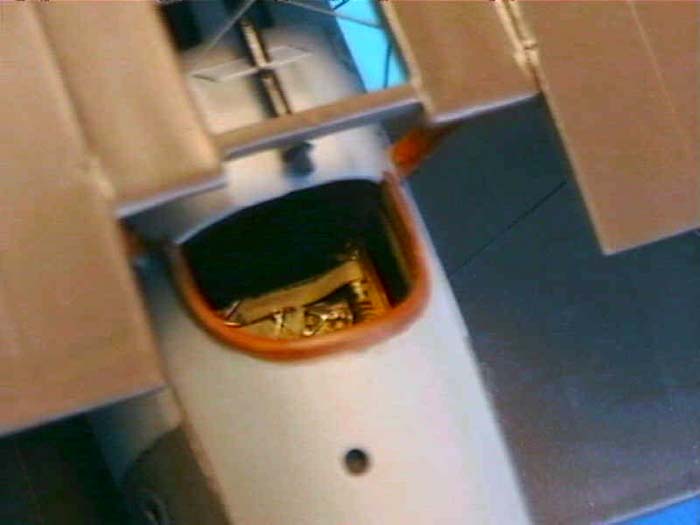 Starting
with the cockpit, I found that Blue Max's white metal took to my rubberized
BSA, Inc. CA quite well. I used gray artists' (OK, sculptor's) modeling
clay on top of a length of flat wood planking as a seat-of-the-pants construction
jig to hold the cockpit frame in place while I tacked it all together
and fitted it to the plastic fuselage flooring, making prompt and liberal
use of CA accelerator spray throughout the process. With the pilot's seat,
stick and rudder pedals now firmly in place, I gave it a few schpritzes
with metal primer and Gunze Mr. Base White. After this had dried, I painted
the stringers and cockpit frame with Model Master Leather (which dried
matte), the 'plywood' floor with Model Master 'sand', colored pencil woodgraining
and clear orange overspray wood simulation technique and did the 'wicker'
pilot's seat with a dark brown which I then hand-highlighted (as opposed
to drybrushing, that is) with a yellowish 'straw' color I mixed from various
Humbrol yellow and khaki/buff shades and then overpainted with thinned
Tamiya Clear Yellow. The cockpit fabric was done, according to instruction,
in a 'rich honey tone' I created with Gunze Sail Color oversprayed, again,
with Tamiya Clear Orange. Seatbelts, throttle and tailskid control wheel
are from Tom's Modelworks WWI British Aircraft Interior set.
Starting
with the cockpit, I found that Blue Max's white metal took to my rubberized
BSA, Inc. CA quite well. I used gray artists' (OK, sculptor's) modeling
clay on top of a length of flat wood planking as a seat-of-the-pants construction
jig to hold the cockpit frame in place while I tacked it all together
and fitted it to the plastic fuselage flooring, making prompt and liberal
use of CA accelerator spray throughout the process. With the pilot's seat,
stick and rudder pedals now firmly in place, I gave it a few schpritzes
with metal primer and Gunze Mr. Base White. After this had dried, I painted
the stringers and cockpit frame with Model Master Leather (which dried
matte), the 'plywood' floor with Model Master 'sand', colored pencil woodgraining
and clear orange overspray wood simulation technique and did the 'wicker'
pilot's seat with a dark brown which I then hand-highlighted (as opposed
to drybrushing, that is) with a yellowish 'straw' color I mixed from various
Humbrol yellow and khaki/buff shades and then overpainted with thinned
Tamiya Clear Yellow. The cockpit fabric was done, according to instruction,
in a 'rich honey tone' I created with Gunze Sail Color oversprayed, again,
with Tamiya Clear Orange. Seatbelts, throttle and tailskid control wheel
are from Tom's Modelworks WWI British Aircraft Interior set.
Perspiration time set in when it was time to fit the fuselage halves over the cockpit structure, which did not seem to want to settle in a level position. At this point, it was time to pull out the trusty ole' power tools to router out the insides of the fuselage half bottoms, and I spent a while longer than I wanted to with the router buzzing away in my hands while light gray plastic snow flurries danced in the air before I could get the halves to go together with the cockpit structure seated satisfactorily.
The next challenge was getting the turtledeck to sit properly on top of the fuselage/cockpit. Left as is, this piece seemed about 1mm too tall and another 1mm too wide on the sides to work, so I used a fine-grained carpenter's dresser to rasp the piece down to the proper dimensions from the bottom up, being EXTREMELY careful to do this evenly along the length of the piece to preserve the shallow arc along the bottom where it must interface with similarly arced areas on both sides of the fuselage. Don't worry if this passage seems a bit confusing right now. When you have the actual kit in your hands, you'll see exactly what I'm talking about.
 The
last major headache of the kit was seating the white metal rotary engine
properly and covering it with the white metal cowling while making sure
that both of these pieces fit snugly with the plastic fuselage. All of
this made for more happy hours of grind'n'dry-fit before everything went
together satisfactorily. Again, these operations are not covered at all
on the instruction sheet. You have to intuit/eyeball it all, praying to
the Muse of Modeling and Ray Rimell for guidance. In the meantime, don''t
even THINK about touching that bottle of CA before you've dry-fitted and
looked at the joint from every possible angle, all the while comparing
what you see with photos and plans in the Datafile.
The
last major headache of the kit was seating the white metal rotary engine
properly and covering it with the white metal cowling while making sure
that both of these pieces fit snugly with the plastic fuselage. All of
this made for more happy hours of grind'n'dry-fit before everything went
together satisfactorily. Again, these operations are not covered at all
on the instruction sheet. You have to intuit/eyeball it all, praying to
the Muse of Modeling and Ray Rimell for guidance. In the meantime, don''t
even THINK about touching that bottle of CA before you've dry-fitted and
looked at the joint from every possible angle, all the while comparing
what you see with photos and plans in the Datafile.
 After
these giddily breathtaking romps through Modeling Adventureland, the rest
of the construction was pretty straightforward, and should give no problem
to modelers with a couple of simple injection kits under their belts.
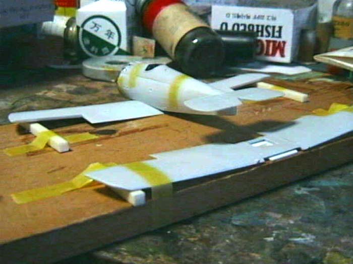
Proper wing dihedral angle is not provided for in the basic structure
of the kit, so you have to crunch the engineering on your own. In my case,
I opted to build a jig – again on a short length of flat wood paneling
– by placing two pegs of 5mm square plastic rod on their sides at
a distance such as that, by placing the fuselage exactly in between them
and securing same to the plank with double-sided tape, the glue-curing
wings would be propped up at the correct angle. I was able to determine
this distance by placing a ruler along the bottom wing edge of the forward
view in the Datafile schematic drawings. The process was repeated for
the upper wing/center section construction. Again, seeing is believing
– or in this case, understanding – and these steps in the construction
will also become evident with the kit spread out before you.
After
these giddily breathtaking romps through Modeling Adventureland, the rest
of the construction was pretty straightforward, and should give no problem
to modelers with a couple of simple injection kits under their belts.
Proper wing dihedral angle is not provided for in the basic structure
of the kit, so you have to crunch the engineering on your own. In my case,
I opted to build a jig – again on a short length of flat wood paneling
– by placing two pegs of 5mm square plastic rod on their sides at
a distance such as that, by placing the fuselage exactly in between them
and securing same to the plank with double-sided tape, the glue-curing
wings would be propped up at the correct angle. I was able to determine
this distance by placing a ruler along the bottom wing edge of the forward
view in the Datafile schematic drawings. The process was repeated for
the upper wing/center section construction. Again, seeing is believing
– or in this case, understanding – and these steps in the construction
will also become evident with the kit spread out before you.
Lower wings were attached to the fuselage and upper wing sections to center section with 1mm brass rod dowel reinforcement. This kind of operation is fairly S.O.P. for any WW1 kit, but crucial for simple injection.
 The
elevator and horizontal stabilizer section required some minor (and very
careful) fuselage filing to achieve true level. On that note, in the better
interests of your sanity, I would suggest that you refrain from attempting
to achieve any kind of geometrical perfection vis-a-vis lining fuselage,
wings and tail section up perfectly. Given the imperfections inherently
involved in simple injection kit construction, you will be a much happier
camper just eyeballing all the alignment and tweaking by hand where needed,
perhaps with a little help from an extra splash of plastic solvent in
a joint here and there. On this kit, I decided to scratch build the rudder
connecting rod and tailskid assembly working from Snipe photos and schematics
in the Datafile. It wasn't a particular daunting task, requiring only
that I remove about 3mm from the end of the fuselage, block that with
1mm plastic planking on top and bottom and then taper that to match (or,
more technically speaking, to continue) the curve of the fuselage with
a little sanding. A few strips of Evergreen in the right spots and a section
of 1mm brass rod to run up through the assembly and into the rudder and
I was in business.
The
elevator and horizontal stabilizer section required some minor (and very
careful) fuselage filing to achieve true level. On that note, in the better
interests of your sanity, I would suggest that you refrain from attempting
to achieve any kind of geometrical perfection vis-a-vis lining fuselage,
wings and tail section up perfectly. Given the imperfections inherently
involved in simple injection kit construction, you will be a much happier
camper just eyeballing all the alignment and tweaking by hand where needed,
perhaps with a little help from an extra splash of plastic solvent in
a joint here and there. On this kit, I decided to scratch build the rudder
connecting rod and tailskid assembly working from Snipe photos and schematics
in the Datafile. It wasn't a particular daunting task, requiring only
that I remove about 3mm from the end of the fuselage, block that with
1mm plastic planking on top and bottom and then taper that to match (or,
more technically speaking, to continue) the curve of the fuselage with
a little sanding. A few strips of Evergreen in the right spots and a section
of 1mm brass rod to run up through the assembly and into the rudder and
I was in business.
The undercarriage gave me no major problems, either, although I found it a wise move to drill 1mm guideholes for the struts to mate with the fuselage. Khaki polyester thread served as fairly convincing bungee cord after painting, and a few quick passes with a Bic lighter and a carefully-aimed splash of Future were enough to take care of the 'textile fuzzies'. Wheels had some injector pin marks that had to be CAed and sanded.
 I
tackled the painting in usual WW1 kit fashion by doing the completed fuselage/tail
section/landing gear and lower wings as a kind of 'monoplane' unit, with
the upper wing handled separately. Both sections were primed with Gunze
Mr. Base White (lacquer) and finished with Model Master acrylics.
I
tackled the painting in usual WW1 kit fashion by doing the completed fuselage/tail
section/landing gear and lower wings as a kind of 'monoplane' unit, with
the upper wing handled separately. Both sections were primed with Gunze
Mr. Base White (lacquer) and finished with Model Master acrylics.
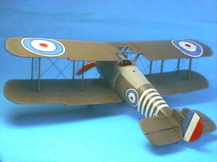
Somewhat war-weary RFC PC10 (FS 24087) upper surface dope was mixed from Model Master Chocolate Brown and RLM Braunviolet. Under incandescent (i.e. yellow) light it looked right on the money, but under the sporting arena lights at the last model show I attended, it looked a bit too gray for my taste. In retrospect, I should have added some more warm olive to give it a bit more tone. Very light drybrushing with a buff color brought out the rib tapes nicely. Battleship Gray (FS 26270) was represented with Model Master Neutral Gray. Clear doped linen was done in Model Master FS 33531 Sand brightened up with a dash of Insignia Yellow and a dusty brown pastel Q-tipped onto the undersurface rib tapes through a 2mm-wide stencil to suggest the brown of the wood poking through the translucent doped linen. Everything except the Battleship Gray areas got a coating of future before and after decaling, then a light overspray of Model Master Flat Clear to scale down the gloss (remember: glossiness has a 'scale effect', also). Shadowing at various points and junctures on the model was done with pastel and/or smudged watercolor pencil.
For rigging, I refrained from my usual Magic-markered fishing line technique because the rigging line in photos of the actual aircraft appears quite thick in diameter – say about as thick as a pencil or a child's crayon. Dividing approximate diameter of same by 48 gave me a rough figure for scale Sopwith rigging of about .2mm, and I just happened to have a batch of straight rod of that gauge collecting dust in my scrap brass box. Another factor in opting for rod rather than 'real' rigging was the sheer nightmare of tangles and curses I was sure an attempt with fishing line was going to turn out to be on a regular ole' rigging hairball like the Snipe.
 Once
the upper wing was on securely, I opted to 'free end' the rigging in a
process where the rods went through .5mm diameter holes drilled through
the lower wings in the approximate direction of a shallow 'receiving hole'
(actually, 'dimple' would be a better name for it) in the lower surface
of the upper wings at the appropriate connection points. Once rigging
length was determined, the rod was pulled back out and cut a fraction
of a millimeter shorter, then given a droplet of viscous CA on the hole
end and run back through with the 'dimple' end left unglued. The logic
behind this is that rod glued at both ends cut exactly to length will
inevitably bend and warp under even the slightest change in upper/lower
wing relative alignment (a sad phenomenon I would suspect many Fairey
Swordfish 'with the works' builders have experienced this spring), but
a rod with one end free will have 'give', and the resiliency of the brass
and absence of gravity effects on such small sections of rod can be left
to take care of keeping the rods straight and true. This may raise many
a modeler's eyebrow, but trust me, it works.
Once
the upper wing was on securely, I opted to 'free end' the rigging in a
process where the rods went through .5mm diameter holes drilled through
the lower wings in the approximate direction of a shallow 'receiving hole'
(actually, 'dimple' would be a better name for it) in the lower surface
of the upper wings at the appropriate connection points. Once rigging
length was determined, the rod was pulled back out and cut a fraction
of a millimeter shorter, then given a droplet of viscous CA on the hole
end and run back through with the 'dimple' end left unglued. The logic
behind this is that rod glued at both ends cut exactly to length will
inevitably bend and warp under even the slightest change in upper/lower
wing relative alignment (a sad phenomenon I would suspect many Fairey
Swordfish 'with the works' builders have experienced this spring), but
a rod with one end free will have 'give', and the resiliency of the brass
and absence of gravity effects on such small sections of rod can be left
to take care of keeping the rods straight and true. This may raise many
a modeler's eyebrow, but trust me, it works.
On a final detail note, the Aldis sight suspended from the upper wing is done with brass tube and wire. Running it through the overhead projector film windshield was a tough little piece of engineering.
Conclusions
I highly recommend this kit for serious and experienced WW1/biplane modelers who want a 1/48 Snipe in their collections but who are unwilling (join the crowd) to go the vac-form route to get one. For the meek-of-heart or beginner WW1 modeler, however, I might suggest that you cut your teeth on a couple of Eduard jobs before you attempt to tackle a kit like this.
In any case, kudos and thanks to Chris Gannon for a well thought-out, well-engineered and just-plain-fun build of a plane that was long overdue a decent kit in 1/48.