
This article originally appeared in the November 1999 issue of Internet Modeler.
 A Colourful Salamander:
Step-by-step build of the
Toko 1/72 Sopwith Salamander

by Pedro Nuno Soares
The Aircraft
Acting in response to a request in late 1917 from the Ministry of Munitions, the Sopwith Aviation Company began to study the adaptation of its most successful aircraft - the Camel - to the role of ground attack aircraft. A set of modifications to the Camel design, which included downward pointing guns and the addition of armor plating to increase survivability of both the pilot and aircraft, ended up producing what was known as the TF.1 (for Trench Fighting). Sopwith then thought about adapting its most recent fighter - the Snipe - to the same role and a new armoured fuselage was designed that when mated to the Snipe's wings produced what was to be known as the TF.2 Salamander. The Salamander was armed with two .303 Vickers guns and had a top speed of 125 mph, provided by the 230hp Bentley BR.2 rotary engine.
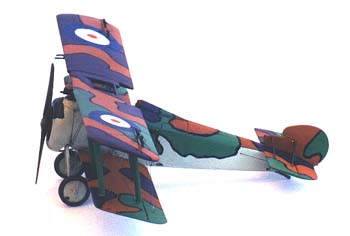
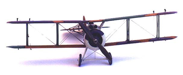
The aircraft were delivered in May 1918, and although too late to see extensive service in the war, some were sent to France for testing. An experimental type of camouflage was also tried on these aircraft. One of which is the subject of the model I built out of the very pleasing TOKO kit that was issued last year as a companion to the same company's Snipe, with which it shares most of the parts.
Putting it together
As most modelers do, I'm sure, when I browse through a good modelling magazine or take a look at the latest edition of Internet modeler (the best of them all) I'm always left with a bittersweet taste in my mouth because it usually reminds me that a long time has already passed since finishing my last model. So, fuelled by what I just saw I start making plans and usually go to the shop and buy another one, which after seeing what it looks like on the inside, is added to the 'to do' pile !!
 On one of those occasions I was reading Scale Models International and
in it there was an article on building TOKO's Sopwith Salamander. My on-going
project at the time, a Sopwith Camel was on hold (as it still is), so
I went to the "to do" pile, retrieved a Salamander and, suddenly, was
all set to go.
On one of those occasions I was reading Scale Models International and
in it there was an article on building TOKO's Sopwith Salamander. My on-going
project at the time, a Sopwith Camel was on hold (as it still is), so
I went to the "to do" pile, retrieved a Salamander and, suddenly, was
all set to go.
Having decided that I would do the experimental camouflage version that was also covered in the SMI article I first had to correct the upper wing profile since the aircraft I wanted to model had unbalanced ailerons. To do this I put strips of masking tape on the wing to act as markers and then filed and sanded away the excess plastic until I was happy with the profile.
Construction then started with the cockpit area and here my out of the box project had the first not so OOB modifications. My main reference (the above mentioned article on SMI) had warned prospective builders like myself to the fact that if one was to glue the lower wing on its normal emplacement on the fuselage the top wing would then completely cover the cockpit and this would not look right. So I had to displace the lower wing 2.5 mm forward. What does this have to do with the cockpit assembly? I hear you ask - Well, Toko supplies a seat, a control column and rudder bar that are meant to be glued on to the centre section of the lower wing which doubles as cockpit floor. Since I was going to bring the lower wing forward, there was no way I could glue all this parts on to their intended locations so I just cut another floor from plastic sheet and glued it to one side of the fuselage, after attaching the seat, column and rudder bar to it.
I also used the kit's instrument panel and the only modification I did to it was to drill holes for the instruments and paint the holes black, while the panel itself was painted light brown and given a touch of a darker brown watercolour pencil. A final coat of Klear floor shine gave it a nice sheen. The machine gun butts were painted black and rubbed with graphite from a 6B lead pencil.
 I knew from past experience with the same manufacturer's Snipe that once
the fuselage halves were glued together not much would be seen inside
the cockpit so that was all the detailing I did.
I knew from past experience with the same manufacturer's Snipe that once
the fuselage halves were glued together not much would be seen inside
the cockpit so that was all the detailing I did.
I painted the sides of the cockpit a brown colour (I reasoned that the armoured plates would be affixed to some sort of wooden shell and not directly to the frame, so there should be no point on painting the interior steel or grey or whatever (I may be wrong of course, but I thought it made sense so I went for it). The moulded on frame was painted in a contrasting shade of brown and traced around with a sharp dark brown watercolour pencil. Painted masking tape seat belts were glued to the seat and that was it.
The two fuselage halves were glued together and set aside to dry. When I looked at it again I noticed that the sprue attachment points to the rear of the cockpit were very prominent and also that if I was to sand the area in order to get a seamless joint, I would do away with the delicate stringer detail on the fuselage so I decided to cover all the area with a .005" panel with the stringers embossed from the inside with a fine ballpoint. Since the panel would stand proud of the fuselage if it were to be simply glued on I scrapped a bit of plastic with a blade until a small step to the rear of the cockpit was apparent. I then dabbed CA on the whole area and attached the scratchbuilt panel which was cut oversize to allow for later trimming. First disaster of a series.
 The glue was too strong and the panel was not properly aligned so I had
to remove it. This was a very difficult task since the plastic was very
thin to begin with and in some places the glue had already set. I finally
managed to get all the panel off and started to scrape away once again
to get rid of the now cured glue. I made a new panel and glued it in place.
This time I got it right but if you look carefully it does stand a bit
proud, because I did not scrape away enough plastic at the front end.
Once the panel was thoroughly dry I sanded the sides flush with the fuselage
sides and was ready to move on.
The glue was too strong and the panel was not properly aligned so I had
to remove it. This was a very difficult task since the plastic was very
thin to begin with and in some places the glue had already set. I finally
managed to get all the panel off and started to scrape away once again
to get rid of the now cured glue. I made a new panel and glued it in place.
This time I got it right but if you look carefully it does stand a bit
proud, because I did not scrape away enough plastic at the front end.
Once the panel was thoroughly dry I sanded the sides flush with the fuselage
sides and was ready to move on.
Before going any further, I planned the rigging and made holes on the wings for it with a .3 mm drill. This is a tedious task but it's much easier to do it while the wings are still separated from the fuselage. If done at a later stage you can exert to much pressure and brake struts or some places might become unreachable to the bit.
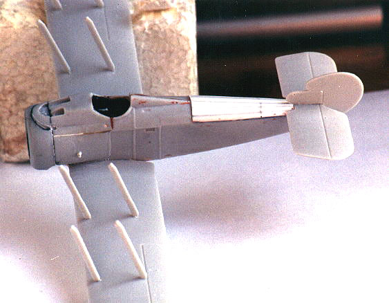
As I said I wanted to move the wings a bit forward and this proved to be a simple operation. It was just a matter of cutting and filling the front end of the slot where they were meant to fit and in five minutes I had it done. I glued the lower wing on (which had the Snipe's exhaust channel removed, as per instructions in the kit) and now I was left with a 2.5 mm gap that I had to fill in. For this I used a bit of plastic strip of the appropriate width and secured it in place with CA that also acted as filler. Incidentally if you use CA as filler do not let it cure for long or you'll have a lot of trouble sanding it flush.
Next came the tailplane and rudder. To help with the alignment and to strengthen the joint I drilled a very tiny hole on the rear of the base of the fin and inserted a bit of a broken .3mm drill bit into it. This not only ensures a good fix but looks better than just butt joining the rudder to the fuselage since I believe the original was mounted in a similar way, a gap between the fuselage and the rudder being apparent on some aircraft types of the era.
On the other end of the fuselage I decided I would use an Aeroclub Bentley engine I had ordered from the manufacturer some time back with this particular kit in mind. Engines are not TOKO's forte as they always look a bit skinny, while the Aeroclub part is an absolute beauty. Since there was no way of gluing the engine on after putting the cowling in place I proceeded to paint the Bentley with several metal shades. After painting I gave it a wash of sepia drawing ink which I find gives engines a nice "oily" finish.
The inside of the cowling was also painted aluminium, the engine was glued on, so was the cowling and on to the struts I went.
I decided to glue the interplane struts at this point since I don't like to add them after painting the wings because there is always the danger of spoiling the finish with glue, or of adherence problems due to the glue sticking to the paint and not to the plastic. So, I added one strut at the time and for this I used what I believe is the best glue in the market "Revell Contacta pro", since it cures not too slowly neither too fast, ensures a strong bond and does not string. The cabane struts were left in the box for now, since they would only be added after gluing the upper wing to the interplane struts.
After a good wash with dish detergent and leaving it all for a day on the bench to dry, I stuffed the cockpit hole with wet tissue paper and was ready to start painting.
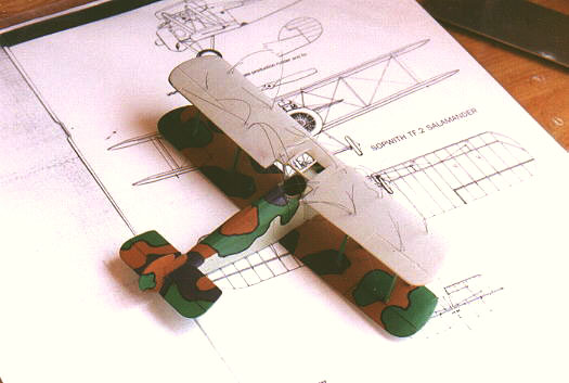
As I said I had planned to do the very colourful experimental camouflage version that was also done by the SMI reviewer.
I decided to stick to the colours that were proposed in that article and the only modification I made was to use Sky type S right from the bottle to replicate the grey-green on the fuselage (and for this I consulted with our expert editor - Thanks again Bob - who said it was ok). So the colours and brands I used were:
 Grey-green - Sky type S - Extracolour X7
Light earth - Leather - Humbrol 62
Green - Mid Green - Humbrol 131
Dark purple earth - Purple - Molak 20 (this equals Humbrol 68)
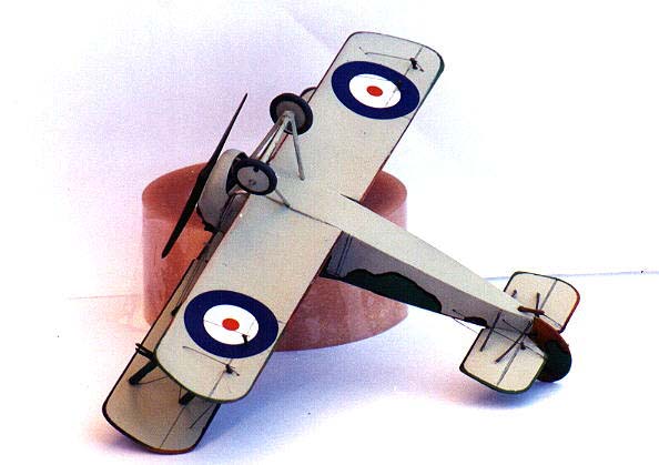
First coat was the grey green on the fuselage and the underside on the top wing. The underside of the lower wing was left unpainted because I would paint it after doing all the rigging since that way it would be possible to better fill, sand and hide the scars from the rigging holes.
When this had dried out I cut a very thin strip of masking tape and masked around the entire profile on the underside of the upper wing leaving something like a 1-1.5 mm gap between the tape and the edge of the wing. The rest of the wing was completely covered in masking tape to prevent any paint reaching it. Why did I do this? On most British aircraft of the period the upper side colour wrapped around the edges of the wings and tailplane and so there would be a strip of this colour all around the underside of the flying surfaces. As such, I could now spray the top colours and thanks to the mask I would get an even thin line on the edges of the wings and tailplane.
The next coat to go on was the brown. Since there would be some of this colour on the top of the fuselage I masked most of the fuselage sides with masking tape and then sprayed the relevant areas as well as the upper surface of the lower wing. After 24 hours I was ready to lay the other colour coats but now I had a problem: since my brush painting absolutely sucks I wanted to find an easy way of masking the irregular patches of colour so that I could safely use my airbrush.
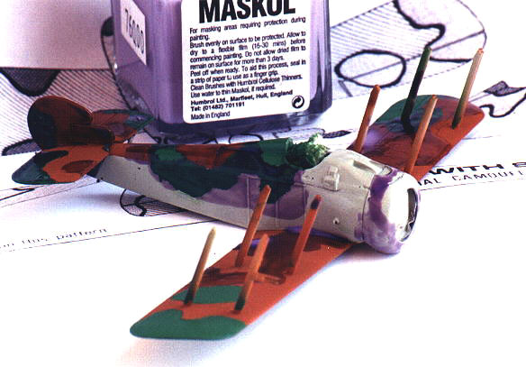
 After some thought I decided that Maskol (Masking fluid manufactured by
Humbrol) would do the trick, and carefully traced the pattern on the kit's
surfaces with a pencil. With the help of a thin brush I "painted" the
areas to be masked with maskol and after it had dried I sprayed the green.
So far so good though I but when the time came to lift the masks I found
out that the maskol coat had adhered to the struts as well and when pulling
it out, 3 struts came along too. So I put them in their places again and
was more careful with the next masking operation (I still had to paint
the purple areas), so as not to let maskol get on the struts. I sprayed
the purple and to my dismay, when lifting the masks another strut jumped
from its natural place so I had to glue it back. In the end, not much
harm done and I was satisfied with the way I had been able to mask all
the camo pattern.
After some thought I decided that Maskol (Masking fluid manufactured by
Humbrol) would do the trick, and carefully traced the pattern on the kit's
surfaces with a pencil. With the help of a thin brush I "painted" the
areas to be masked with maskol and after it had dried I sprayed the green.
So far so good though I but when the time came to lift the masks I found
out that the maskol coat had adhered to the struts as well and when pulling
it out, 3 struts came along too. So I put them in their places again and
was more careful with the next masking operation (I still had to paint
the purple areas), so as not to let maskol get on the struts. I sprayed
the purple and to my dismay, when lifting the masks another strut jumped
from its natural place so I had to glue it back. In the end, not much
harm done and I was satisfied with the way I had been able to mask all
the camo pattern.
Let me just say here that the top side of the upper wing was not sprayed at this time exactly for the same reason that I hadn't painted the underside of the lower wing.
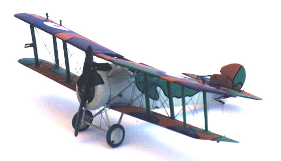
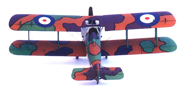
The camo pattern demanded that all the irregular patches of colour should also be outlined in black and this proved to be the easiest part of it all. Guided by a tip from Matt Bittner, I bought a couple of black Sakura Pigma permanent markers and it was just a question of outlining the patches with them. The marker ink flows quite well and since I was using a .005 tip I could easily and calmly build up the outline in several passes.
 With all the major painting done it was time to put the wings on and this
I did with the help of a touch of CA on top of each strut. Just one word
here. It helps if you accentuate the locating holes on the wings with
an appropriate diameter drill bit. That way you'll be sure of a positive
fix.
With all the major painting done it was time to put the wings on and this
I did with the help of a touch of CA on top of each strut. Just one word
here. It helps if you accentuate the locating holes on the wings with
an appropriate diameter drill bit. That way you'll be sure of a positive
fix.
I was now ready to rig and this I did with the help of transparent sewing monofilament, which is tinted a smoke colour that I find very nice since it makes all the wires much more apparent than the normal fishing colourless monofilament I had been using till then.
Rigging through pre-drilled holes has the advantage of strengthening the wing assembly since the wires become part of structure also and this is so true that when pulling tight one of the wires on one of the outer bays I pulled too hard and both struts on that bay broke in two. Luckily I had a piece of contrail strut stock of the appropriate size laying around so it was just a matter of cutting new struts, putting them in place with a touch of CA on both ends and painting green as all the others. 5 minutes got me going again.
When all the rigging was finished I filled in any holes left on the wings with liquid paper, sanded smooth and was ready to paint the outer surfaces of the wings. First I did the lower wing, carefully masking around its profile with strips of masking tape glued on to the leading edges (the strips were wide enough to act as barriers to protect the rest of the kit). To achieve the top colour outline on this wing, when spraying the top colours I had also sprayed a thin strip all around the perimeter of the wing, and now I masked it with a very thin strip of masking tape. So when the Sky paint had dried I removed the masking tape and Voilá: a nice three colour outline appeared on the edges.
Next I painted the top wing (first the brown and then after masking with maskol again I was able to do the green and the purple in one single spaying session).
 After all had dried I brushed on the outer surface of the top wing a couple
of coats of Klear to prepare it for the decals that were then put in place
with the help of some more drops of this fantastic stuff. This way you'll
be sure your decals will never silver.
After all had dried I brushed on the outer surface of the top wing a couple
of coats of Klear to prepare it for the decals that were then put in place
with the help of some more drops of this fantastic stuff. This way you'll
be sure your decals will never silver.
The control horns (fashioned from small pieces of telephone wire flattened in a small table vise) were then added to pre-drilled holes and the rest of the rigging was now done.
The Salamander was very nearly ready to go and all that was left to do was to add the u/c (that fitted ok in spite of my having pushed the lower wing forward), with its three wires and also a small strut that connects the cowling to the fuselage, which I replicated with the use of the same stuff I had used for the horns.
The bracing struts on the tailplane were added with pieces of thick fishing line (piano wire would be more appropriate I guess, but I had none).
The last part to be put in place was a propeller, and for this I used the aeroclub prop that came in the same bag as the Bentley, which I painted in brown enamel and then worked on with watercolour pencils until I got to a colour I was satisfied with. A couple of coats of Klear rolled rapidly on with the help of a cotton swab gave it a very nice shine and -(you have to make sure that on the first coat you only roll the swab once over the surface or the watercolour will dilute and you'll loose the effect) - And that was it.
Conclusion
I'm very happy with the way my Salamander came out and I think it would not look out of place if displayed side by side with Michael Kendix's beautiful Sopwith Snipe , since they are so closely related
One last word to acknowledge the help that I got also from fellow modeller Len Smith who along with Bob Pearson took care of the doubts I had during the construction phase. Thanks guys!
References:
Sopwith Salamander - Scale Models International, June/July 99