
This article originally appeared in the October 1998 issue of Internet Modeler.
|
SCRATCHBUILT
BEAUTY CREATING A HANDLEY-PAGE 0/400 IN 1/48 SCALE By Robert Karr |
|
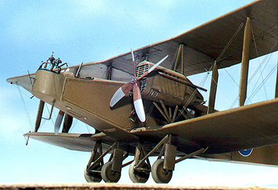
The Airplane: The Handley Page 0/400 was the ultimate
wartime development of the original 0/100 "Bloody Paralyser",
built for Britain's Royal Naval Air Service in 1915. A huge, slab-sided,
twin engined biplane of conventional wood, wire and fabric construction,
the 0/400 became the mainstay heavy bomber in one of the first "strategic"
air The Model: I like scratchbuilding. Few things
in the modelbuilding world are more satisfying than taking raw hunks
of wood, plastic sheet, assorted wads and gobs of glue, putty and
paint, and creating a miniature version of an actual object. One
of the most exciting parts of the process is figuring out "What
shall I build next?". The Handley Page 0/400 has been one of
my favorites for years, with its ugly-beautiful lines that seem
to Research: Whether kit or scratch, the first thing is to gather references -- the more the better and, when working without a net, "more" can't be stressed enough. A flat sided, angular airplane would seem to be a simple thing, but after devouring a stack of research 18" thick, and having the model almost 95% finished, I was still scrambling for details. I was haughty and self assured: "Of course I've got what I need, no problem". Wrong! Starting with pretty good drawings
by Colin Owers and some detail photos, I went to Construction: Anxiety-driven complications arose from my decision to make sure that no probing by the "penlight brigade" would reveal any non-modeled areas, no matter where the brigade decided to insert their instruments! This meant that almost the entire fuselage interior would have to be made, which comes out to only a few hundred parts going into the bomb cells, fuel tanks and fuel management systems, which all had to be researched, drawn and built and almost all would never be seen again after the fuselage was closed up. BUT.... they are in there if anyone ever assaults the poor model with dental mirror and flashlight in hand. The Fuselage Structure: All this was waiting for me when
construction actually got going. I started the old fashioned way:
building the fuselage right over the plans. Taping wax paper over
a profile of the fuselage structure, I proceeded to build each side
from HO railroad scale Holes were drilled using a homemade
bit. A 1" long section of bamboo skewer, available at most
supermarkets, had a 3/8" long piece of .008" steel guitar
string crammed into one end, leaving about half sticking out. Slathering
on a generous glop of Zap-a-Gap, I had a fine bit that would do
this gentle job. Not perfectly centered, one Internal Detail: The internal stuff holds no surprises
for anyone with an easy conversion or two under their belt. Sprue,
bits of sheet plastic, wire, the usual. The seat cushions are epoxy
Exterior Detail: The model was built inside out, all
the internal detail being incorporated before the outer skin was
applied. The skin is .015 plastic from the nose turret back, and
the nose itself is covered in 1/64 aircraft plywood. The various
windows punctuating the sides After the fuselage was closed up, duplicating the lacing was next -- a most labor-intensive step. Fine lines were incised where the "fabric panels" came together and each lace was "painted" over the slit with a tiny brush loaded with a mix of yellow aliphatic resin glue, and whatever acrylic color happened to be handy; this color merely tinted the glue so I could see where I'd been! The Wings: The wings were built in the traditional
method of plastic skin over a wood core. .015" plastic sheet,
with ribs embossed from the inside using an old ball point pen,
was glued over a balsa plank that had been shaped to the correct
airfoil and planform, but a little smaller to make up for the extra
thickness of the plastic. Heavy dowels were After some general cleanup of leading and trailing edges, the next laborious task was started. I wasn't truly happy with the ribs -- they just weren't prominent enough. To remedy this and to add another extra dollop of realism, I added rib tapes. Many of us old geezer modelers still think of fabric covered wings as having a great deal of "sag" between ribs, because that's the way Aurora and other companies presented these wings. But except for a few isolated airplanes, and mainly early in the war, airplane fabric was taut with almost no sag. The most visible remaining evidence of ribs was the tapes that were doped and stitched over each rib. To simulate these, I masked off EVERY rib station, top and bottom of each wing, and airbrushed several heavy coats of Testors oil base neutral gray. After drying and removing the tape, very prominent "tapes" stood proud above the surface, to be gently sanded to the correct height. All the tail surfaces were built the same way as the wings. Struts: Struts were made in a variety of ways. The mainplane items are wire core plastic rod, built up with thin bass wood sheet fairings, the whole covered in Zap-a-Gap, sanded and then painted with thick paint to sculpt the fabric wrappings that are evident in photos of the real objects. The cabane, tail, and landing gear struts are made from the thickest bamboo skewers I could find- a pack that contained sticks up to 3/16" diameter. From these, I shaved thin planks of airfoil section, cut to length and shaped, and glued wire pins into drilled holes in each end of each finished strut. Engine Nacelles: Sub-Assemblies Come Together: Most subassemblies were pre-painted and the major components were ready to mate. The aforementioned spar stubs of the bottom wing were slathered in 5 minute epoxy and inserted into holes in the fuselage. Still having a few minutes left before the glue set up, I taped the monster down on the kitchen table over a gridded drawing of right angles so I could make sure everything was right and true. The extra work time epoxy offers over C/A allows for adjustment, and after tweaking the top view and getting the dihedral just so, I stabilized everything with telephone books, cookie jars, and whatever else I could grab to hold everything in place. Although called "5 minute epoxy", I always like to allow a little more time for curing, so for the next couple of hours, I wandered around the house aimlessly, resisting the temptation to "Just check a little". When I finally gave in and extracted the model from all its jigs and braces, I was relieved to the point of offering a small prayer of thanks -- everything had set up in line and in tune! Assembling The Wings: A deep breath, and it was time for
the real make-or-break step...attaching the top wing! Giving all
the interplane struts one final length check, I was ready. The wire
cores For the cabane struts, I snipped off most of the wire ends and glued these into small dimples I had previously made in the fuselage and bottom of the top wing. The tail surfaces were installed in the same fashion, with the rudders acting as the major struts. Rigging: The functional rigging was accomplished
with different gauges of mono fishing line, pulled through holes
drilled through all major components. Minor adjustments were still
possible at this stage so I could pull the whole into alignment.
Each place where a rigging line came through received a very generous
slopping of Krazy Glue. In my After rigging, my 0/400 looked as if it was sprouting strange alien foliage until I snipped off all the rigging ends. Snipping finished, I still had quite a bit of cosmetic fine tuning: glue blobs that needed grinding down and holes that needed to be filled. Luckily, before I started this thing, I mixed up two 35mm film canisters (Kodak -- they seal better than other brands) of my basic WW I British P.C.10 khaki-O.D. brownish green color so matching the color over surface dings wasn't much of a problem. I needed a lot because almost everything on the model was painted with this color -- don't ask for my color formula! I just mixed a bunch of Testors ModelMaster oil base stuff until it looked correct. Even the colors were truly "scratch" as I started with basic red, yellow, blue, black and white. Final Details: At this point I had a perfectly strong structure ready for the final details. The landing gear sticks were glued into place as was the tail skid, all made from bamboo. The wheels are?????? I can't remember from what they sprang. I do remember it was a little difficult to get a good-looking Handley Page wheel. They're fatter than the average WWI shape, but not fat enough to substitute a WW II tire. Also, no plumbing "o" ring would do the job. But what, oh what, did I use? Beats me! By now I was getting sick of the whole thing. I never wanted to see the words "Handley-Page" again. The Wife told me that if I gave up now, after putting in all this time with nothing to show, she'd have to rethink my position in the cosmos, and threatened to change said position. A gentle re-introduction to resumed construction was called for. The fuel and oil lines! All external
fuel lines were made from thin string soaked in cheap craft acylic
paint. I first coated the string with aliphatic resin glue and then
The engine nacelles were mounted on their little forests of bamboo struts, hand carved mahogony props were installed, huge aileron cranks( more bamboo!) glued on, control line rigging put on and in, and now I sat back to see what's what. The Home Stretch: Hmmm... where DO those aileron control
wires exit the fuselage? On no -- I should've put the fuselage walk
rails on before now. Ouch! What else have I missed? Uh... generators...
fuel pumps (those little cups spinning through those dumbbell shaped
openings in the fuselage sides, like anemometers), pitot tubes,
wing tip landing flares, gas caps on the top wing, rope pull handles
on the rear fuselage, nose bomb sight mount -- the list seems endless.
I'm again ready to have a breakdown; none of these items are difficult
to construct -- bits of plastic sprue, a piece of guitar string
here and OK, back to it, one final push. The last bits are made and stuck on. Decals are custom sprayed on clear stock and applied. I let everything rest for a few days. British WW I dopes went on glossy but dulled out in a short time, so I shot a mix of 50-50 dull-gloss over the top and let this dry, to be followed by an overall mist of the weakest light gray sprayed at high pressure. This gave the final look of a large airplane with uneven coloration. 0/400s were hangared when possible, but the amount of exposure they did receive, coupled with the difficulty in getting an even color on so much surface made them... not blotchy... but... uneven. That's the best word. An oil streak here and a mud blotch there, and it's finished. The Epilogue: It was finished!!! I hated it. I thought it was the worst piece of #$#%$# I'd ever made. I couldn't look at it. But slowly, I began to appreciate the beast. Maybe I did accomplish a little of what I set out to do. Another contest was looming. A big one. One whose top prize was a ride in a P-51 Mustang. My killer instinct was rising now. Allright, this thing IS more than OK -- this thing has a shot. I'm gonna win that prize and give the ride to the Kid, being a firm believer in the idea that every 13-year old needs to be upside down at 350mph at least once. The award ceremony begins. Good models winning good trophies. Finally down to the "Best of Show". The Handley-Page wins!!!! Yipe! I get to send the Kid off in a screaming metal tube at several hundred miles per hour for who knows how long! Whew! In almost fairy-tale fashion all went well, the Kid got his ride and landed intact with a smile that almost had to be surgically removed.
|
||
| Stats, Specs, and Colors |
|
|
| Notes and sources: |
|
|
 campaigns in history. During the summer and autumn of 1918, Handley
Pages of the RAF's Independent Force took the war into the German
homeland, bombing factories and railyards and other fat targets
far behind the front lines. After the November 11, 1918 Armistice,
several examples of the beast were fitted with up to 16 seats and
used as airliners, trading bombs and bullets for passengers and
mail.
campaigns in history. During the summer and autumn of 1918, Handley
Pages of the RAF's Independent Force took the war into the German
homeland, bombing factories and railyards and other fat targets
far behind the front lines. After the November 11, 1918 Armistice,
several examples of the beast were fitted with up to 16 seats and
used as airliners, trading bombs and bullets for passengers and
mail.  suggest some sedate and squat building, rather than a flying machine.
Also, thinking that an affordable kit in at least 1/48 scale was
a pipe dream, I decided an 0/400 must be built. The ancient (going
on 30 years!) and venerable Airfix Handley Page is in 1/72 scale
so if I wanted a real "Bloody Paralyser" of a model, scratchbuilding
was the only way to go.
suggest some sedate and squat building, rather than a flying machine.
Also, thinking that an affordable kit in at least 1/48 scale was
a pipe dream, I decided an 0/400 must be built. The ancient (going
on 30 years!) and venerable Airfix Handley Page is in 1/72 scale
so if I wanted a real "Bloody Paralyser" of a model, scratchbuilding
was the only way to go. 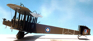 work. The overall size and shape quickly formed on my drawing board.
So far, so good; I started construction and thought I could pick
up the details later. Big mistake! As work progressed, I started
finding more anomalies in individual 0/400s. Fuel systems varied
from plane to plane; several nose configurations were noted; rear
gun mounts could take many forms; maintainence platforms above the
engine nacelles presented themselves only to disappear on another
machine. All of these had severe visual repercussions on the final
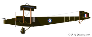
product. The markings were in fact decided because I happened to
luck into three shots of the same airplane taken at the same time,
from different angles.
work. The overall size and shape quickly formed on my drawing board.
So far, so good; I started construction and thought I could pick
up the details later. Big mistake! As work progressed, I started
finding more anomalies in individual 0/400s. Fuel systems varied
from plane to plane; several nose configurations were noted; rear
gun mounts could take many forms; maintainence platforms above the
engine nacelles presented themselves only to disappear on another
machine. All of these had severe visual repercussions on the final
product. The markings were in fact decided because I happened to
luck into three shots of the same airplane taken at the same time,
from different angles. 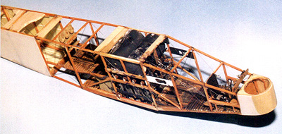 basswood lumber- 2"x3"s, 3"x3"s, and 4"x4"s.
Before using any of this stock, I treated it to a coat of water-based
light brown stain with a top coat of thinned Testors acyrlic gloss,
sanded lightly to de-fuzz the mess. Positioning each stick with
straight pins, all joints got a blob of thick Zap-a-Gap. The two
sides were then jigged up on a balsa block, held once again with
pins, and the cross members cut to size and glued in to form the
basic box girder. My structure was now starting to resemble something
belonging to an airplane, but it was a little wobbly and needed
rigging between all members at all joints, just like the real thing.
basswood lumber- 2"x3"s, 3"x3"s, and 4"x4"s.
Before using any of this stock, I treated it to a coat of water-based
light brown stain with a top coat of thinned Testors acyrlic gloss,
sanded lightly to de-fuzz the mess. Positioning each stick with
straight pins, all joints got a blob of thick Zap-a-Gap. The two
sides were then jigged up on a balsa block, held once again with
pins, and the cross members cut to size and glued in to form the
basic box girder. My structure was now starting to resemble something
belonging to an airplane, but it was a little wobbly and needed
rigging between all members at all joints, just like the real thing.
 does need to poke a slight centering dimple at the place where a
hole is desired. Chucking up this thing in a cordless Dremel, I
made precise holes at every place in the box where two or more structural
members met. The real fun was beginning: I ran so-called "invisible
thread" -- prepainted a steely dark gray -- through all the
holes and pulled the structure true. Brand name Krazy Glue was generously
spread over all points; now the box was starting to show some strength.
Part of the bargain in this type of construction is learning just
how strong a bunch of sticks can be. The logic of actual airplane
construction techniques start to become apparent!
does need to poke a slight centering dimple at the place where a
hole is desired. Chucking up this thing in a cordless Dremel, I
made precise holes at every place in the box where two or more structural
members met. The real fun was beginning: I ran so-called "invisible
thread" -- prepainted a steely dark gray -- through all the
holes and pulled the structure true. Brand name Krazy Glue was generously
spread over all points; now the box was starting to show some strength.
Part of the bargain in this type of construction is learning just
how strong a bunch of sticks can be. The logic of actual airplane
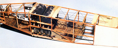
construction techniques start to become apparent! 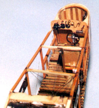 putty, all the slatting is HO lumber. Also, this center section
received all manner of hidden wood braces and blocks, because of
the extra strength needed to anchor the wings. The twin main fuel
tanks, resembling large trash cans, were sawn from 3/4" hardwood
dowel. After grain filling and painting and installation, they helped
stabilize and strengthen this structurally important section of
the model. The almost invisible bomb cells were cobbled up from
plastic rod, .005 plastic sheet, and Krazy Glue saturated typing
paper, sanded smooth. A few words about different C/A adhesives:
for general construction I use Zap-a-Gap Thick, but for sticking
invisible thread and nylon mono fishing line, I use good ol' drug
store Krazy Glue. It sticks better to nylon, and after curing, doesn't
have as much "stretch" in it; a glued line pulled taut
will stay taut. It also behaves better when I make my typing paper
stock.
putty, all the slatting is HO lumber. Also, this center section
received all manner of hidden wood braces and blocks, because of
the extra strength needed to anchor the wings. The twin main fuel
tanks, resembling large trash cans, were sawn from 3/4" hardwood
dowel. After grain filling and painting and installation, they helped
stabilize and strengthen this structurally important section of
the model. The almost invisible bomb cells were cobbled up from
plastic rod, .005 plastic sheet, and Krazy Glue saturated typing
paper, sanded smooth. A few words about different C/A adhesives:
for general construction I use Zap-a-Gap Thick, but for sticking
invisible thread and nylon mono fishing line, I use good ol' drug
store Krazy Glue. It sticks better to nylon, and after curing, doesn't
have as much "stretch" in it; a glued line pulled taut
will stay taut. It also behaves better when I make my typing paper
stock. 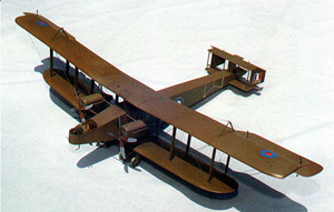 and bottom were sliced out and covered in cigarette package cellophane
that had first been dipped in Future floor wax. This material nicely
duplicated the wrinkly glazing of the original. Frames were made
from my stock of C/A saturated and sanded typing paper. The gun
ring is one of the few non-scratch items, being an old Aurora gun
ring from some I-don't-know-what kit.
and bottom were sliced out and covered in cigarette package cellophane
that had first been dipped in Future floor wax. This material nicely
duplicated the wrinkly glazing of the original. Frames were made
from my stock of C/A saturated and sanded typing paper. The gun
ring is one of the few non-scratch items, being an old Aurora gun
ring from some I-don't-know-what kit. 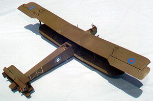 fitted into holes at the ends of the wing sections where the spars
would be so that I would have sturdy gluing points when final assembly
time rolled around.
fitted into holes at the ends of the wing sections where the spars
would be so that I would have sturdy gluing points when final assembly
time rolled around. 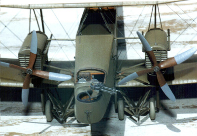 The engine nacelles started as rough bass wood blocks that were
tortured into shape and skinned with plastic to avoid the always-unwholesome
task of grain-filling. The exhaust manifolds were made from flame-broiled
and bent plastic tube. The radiators are the usual sheet plastic;
next time I think I'll use brass! (also note that the engine instruments
are mounted in the nacelles, rather than the cockpit.)
The engine nacelles started as rough bass wood blocks that were
tortured into shape and skinned with plastic to avoid the always-unwholesome
task of grain-filling. The exhaust manifolds were made from flame-broiled
and bent plastic tube. The radiators are the usual sheet plastic;
next time I think I'll use brass! (also note that the engine instruments
are mounted in the nacelles, rather than the cockpit.) 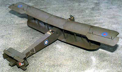 in the struts fitting into holes drilled into the solid wood inside
the wing gave strong joints. First, I taped the airplane solidly
to the table, stuck the inmost pair of struts into the bottom wings
on each side, got out the triangles and squares, sighted in all
the angles and set one strut at a time into position with Zap-a-Gap.
When I had these four struts solid, I removed the model from its
sticky prison so I could handle it freely. I placed the top wing
onto the four struts, wishing I had four hands; when all was right
and true, I locked it up with tape. Now with a few drops of Zap-a-Gap,
my wing was solid and I could continue working my way outward one
side at time through each pair of struts.
in the struts fitting into holes drilled into the solid wood inside
the wing gave strong joints. First, I taped the airplane solidly
to the table, stuck the inmost pair of struts into the bottom wings
on each side, got out the triangles and squares, sighted in all
the angles and set one strut at a time into position with Zap-a-Gap.
When I had these four struts solid, I removed the model from its
sticky prison so I could handle it freely. I placed the top wing
onto the four struts, wishing I had four hands; when all was right
and true, I locked it up with tape. Now with a few drops of Zap-a-Gap,
my wing was solid and I could continue working my way outward one
side at time through each pair of struts. 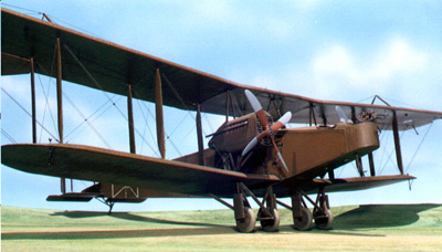 world, it's much more important to get everything lined up and sturdy
and worry about body work later.
world, it's much more important to get everything lined up and sturdy
and worry about body work later. 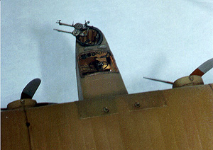 The guns were scratched from plastic rod and tube,
as were their mounts- except for the serrated arc on the nose ring
-- that's a Tom's Modelworks brass part. I should tell you that
at this point laziness or exhaustion attacked and I made the rear
Lewis gun without an ammo drum; I couldn't face it. The model was
already three weeks late for a contest that I had planned on using
for the public debut.
The guns were scratched from plastic rod and tube,
as were their mounts- except for the serrated arc on the nose ring
-- that's a Tom's Modelworks brass part. I should tell you that
at this point laziness or exhaustion attacked and I made the rear
Lewis gun without an ammo drum; I couldn't face it. The model was
already three weeks late for a contest that I had planned on using
for the public debut. 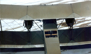 sanded it. (Egad! The man sands string!) This
de-fuzzes it, and then I put on five, maybe six heavy coats of cheap
craft acrylic paint. Now I had miles of flexible line.
sanded it. (Egad! The man sands string!) This
de-fuzzes it, and then I put on five, maybe six heavy coats of cheap
craft acrylic paint. Now I had miles of flexible line. 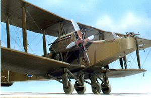 there -- but there are just too many for my brain to get a handle
on. By now, I HATE scratch-building. The Wife says "Just
step back, take a look at it, it's turning out great and you're
in the home stretch". The Son comes out of his lair, sniffs
around and makes about the same pronouncement.
there -- but there are just too many for my brain to get a handle
on. By now, I HATE scratch-building. The Wife says "Just
step back, take a look at it, it's turning out great and you're
in the home stretch". The Son comes out of his lair, sniffs
around and makes about the same pronouncement. 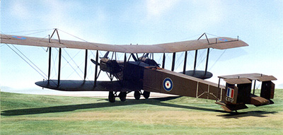 Contest day dawns: load the thing into the van,
get to the contest, sign in, check out the other entries. My heart
sinks -- there are some GREAT models here. Oh well, maybe I'll come
home with a trophy or something although I'm usually not that trophy-hungry.
My ordinary contest mindset is geared toward having a good day hanging
out with fellow modellers, getting some good deals at the vendors,
and if a win comes my way, it's just gravy. But this day was different:
I was on a mission. The Kid NEEDS this ride.
Contest day dawns: load the thing into the van,
get to the contest, sign in, check out the other entries. My heart
sinks -- there are some GREAT models here. Oh well, maybe I'll come
home with a trophy or something although I'm usually not that trophy-hungry.
My ordinary contest mindset is geared toward having a good day hanging
out with fellow modellers, getting some good deals at the vendors,
and if a win comes my way, it's just gravy. But this day was different:
I was on a mission. The Kid NEEDS this ride.