
This article originally appeared in the July 2000 issue of Internet Modeler.
 Building
Artur's 1/72nd Scale Phönix D.III
Building
Artur's 1/72nd Scale Phönix D.III

by Michael Kendix
Introduction
The Phönix D.III was developed from the Phönix D.II and IIa.. According to Grosz et al., the modifications included a "revised wing planform and a fuselage designed for accessible machine guns mounted at eye level." (page 126). It was also up-engined from a 200 hp to a 230 hp Hiero engine. A hundred were approved for production and were scheduled to be delivered on October 27, 1918, however, there was a delay, and the war's end put a stop to the planned delivery. In 1919 and 1920, the Swedish Army Air Force purchased a total of 20 Phönix D.IIIs; number 947 can be seen at the Swedish Air Force Museum. In a previous edition of Internet Modeler, Bob Pearson provided an in-box review of this kit. My own impressions of this kit were similar to Bob's, that is, the resin parts looked crisp and were finely detailed. Never having built a resin kit before, I was curious as to how things would go.
First Steps
 The
first thing I had to decide before starting construction of this kit was
the particular aeroplane I wanted to build. The top wing's upper surface
contains two fuel tanks and these were only found on the Swedish version
of the Phönix D.III; the model would have to built with Swedish markings
and would represent a machine from the early post-World War One era. I
am more interested in representing World War One era aeroplanes and had
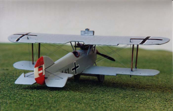
seen a picture of J.41 on page 128 of Grosz et al's book. I found the
markings to be more colourful and attractive than the Swedish version,
in particular, the Austro-Hungarian Crown and Cross marking on the red-and-white
striped vertical tail. Unfortunately, this meant I had to remove the upper
wing fuel tanks and make the ribs that would have been there otherwise;
a more time consuming option, relative to the Swedish version.
The
first thing I had to decide before starting construction of this kit was
the particular aeroplane I wanted to build. The top wing's upper surface
contains two fuel tanks and these were only found on the Swedish version
of the Phönix D.III; the model would have to built with Swedish markings
and would represent a machine from the early post-World War One era. I
am more interested in representing World War One era aeroplanes and had
seen a picture of J.41 on page 128 of Grosz et al's book. I found the
markings to be more colourful and attractive than the Swedish version,
in particular, the Austro-Hungarian Crown and Cross marking on the red-and-white
striped vertical tail. Unfortunately, this meant I had to remove the upper
wing fuel tanks and make the ribs that would have been there otherwise;
a more time consuming option, relative to the Swedish version.
My first task was to clean up the wings and fuselage, and remove the smaller parts from their resin wafers. This proved to be quite straightforward; everything cleaned up well. There were no instructions, so I had to study various pictures prior to construction in order to make sure I knew what to do with each part. Except for two small prong-shaped pieces, I worked out which pieces went where. If anyone knows what these two 'extra' pieces represent, I would be glad to hear from them.
Reworking the top wing
 After
removing the aileron control surfaces, I took the Dremel and the top wing
part outdoors, put on my dust mask (resin dust should not be inhaled)
and switched on the Dremel. The resin was quite hard and sanding off the
wing tanks took some time. After most of the tank was removed with the
Dremel, the surface was smoothed off with successively finer grades of
sandpaper. The next job was to replace the wing ribs. This was done using
the method described by Candice Uhlir in her build-up of the Smer 504K
at Hyperscale or Modelling
Madness. I placed strips of masking tape either side of where the
rib had to go, leaving a very narrow space for the rib. I then brushed
on a coat of 'Mr. Surfacer 1000'. This process required a couple of attempts.
The first time, I airbrushed the wing and realized I had left too much
'Mr. Surfacer' on the wing, and the ribs I had made were more accentuated
than the ones already on the kit. I easily removed the water-based acrylic
paint with Q-tips dipped in Windex. The second time, I left only a 'hint'
of ribbing and this seemed to work; perhaps my ribs were a little under-stated
compared to the kit's this time, but I think it's preferable to err on
that side.
After
removing the aileron control surfaces, I took the Dremel and the top wing
part outdoors, put on my dust mask (resin dust should not be inhaled)
and switched on the Dremel. The resin was quite hard and sanding off the
wing tanks took some time. After most of the tank was removed with the
Dremel, the surface was smoothed off with successively finer grades of
sandpaper. The next job was to replace the wing ribs. This was done using
the method described by Candice Uhlir in her build-up of the Smer 504K
at Hyperscale or Modelling
Madness. I placed strips of masking tape either side of where the
rib had to go, leaving a very narrow space for the rib. I then brushed
on a coat of 'Mr. Surfacer 1000'. This process required a couple of attempts.
The first time, I airbrushed the wing and realized I had left too much
'Mr. Surfacer' on the wing, and the ribs I had made were more accentuated
than the ones already on the kit. I easily removed the water-based acrylic
paint with Q-tips dipped in Windex. The second time, I left only a 'hint'
of ribbing and this seemed to work; perhaps my ribs were a little under-stated
compared to the kit's this time, but I think it's preferable to err on
that side.
Engine, Cockpit and Fuselage
 The
engine is well detailed but contained some pinholes, which I duly filled
with Squadron White putty. I then added some plastic rod to look like
pipes to the engine, to try and make it look as much like a Hiero engine
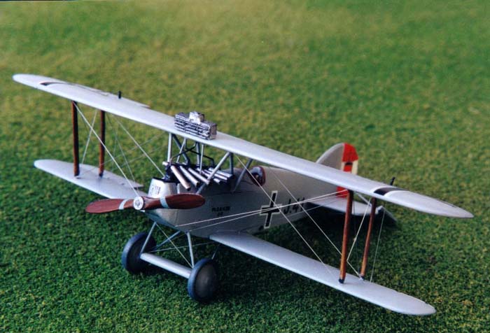
as possible. The kit provides six small pieces of resin rod for the port
side engine intakes. According to the photographs and diagrams in Grosz
et al., the intakes are not lined up parallel to each other; those at
the front are angled down lower than those aft, each one being slightly
less angled then the one in front of it, giving a sort of 'fanned' effect.
I do not know why this was done, possibly it was necessary to bend and
redirect them in order to get them to fit around the N-shaped cabane struts,
which was certainly a problem I experienced.
The
engine is well detailed but contained some pinholes, which I duly filled
with Squadron White putty. I then added some plastic rod to look like
pipes to the engine, to try and make it look as much like a Hiero engine
as possible. The kit provides six small pieces of resin rod for the port
side engine intakes. According to the photographs and diagrams in Grosz
et al., the intakes are not lined up parallel to each other; those at
the front are angled down lower than those aft, each one being slightly
less angled then the one in front of it, giving a sort of 'fanned' effect.
I do not know why this was done, possibly it was necessary to bend and
redirect them in order to get them to fit around the N-shaped cabane struts,
which was certainly a problem I experienced.
I used the materials provided in the kit for the cockpit; namely, the control stick, instrument panel and foot rudder. I added seat belts using strips of lead foil from a wine bottle and buckles from a Tom's Modelworks photoetch interior. I cannot remember which nationalitys interior I used; there is none for Austro-Hungarian aeroplanes. The interior was painted grey, and the frame, seat and instrument panel were painted 'Leather Brown'.
 It
was my impression that the cockpit area is a little too small since the
seat almost touches both sides of the fuselage. Before closing the fuselage,
the engine housing area in the front fuselage was sanded out as much as
possible using a Dremel. The lower and front parts of the engine were
sanded away in order to be able to close the fuselage; none of this surgery
was visible when the fuselage was closed. Once glued, the fuselage seams
required filling with super glue. Once the glue was sanded down, some
faint seam lines remained, and these were filled with some typewriter
correction fluid.
It
was my impression that the cockpit area is a little too small since the
seat almost touches both sides of the fuselage. Before closing the fuselage,
the engine housing area in the front fuselage was sanded out as much as
possible using a Dremel. The lower and front parts of the engine were
sanded away in order to be able to close the fuselage; none of this surgery
was visible when the fuselage was closed. Once glued, the fuselage seams
required filling with super glue. Once the glue was sanded down, some
faint seam lines remained, and these were filled with some typewriter
correction fluid.
Wings, Tail and Struts
The lower wings were then attached to the fuselage. Two small holes were drilled into both the fuselage sides and the inside edge of the wing root. Then small lengths of 28 gauge copper wire were inserted into the holes in the wing root, and the other end of the wires were then inserted into the holes in the fuselage. This gave the wing-fuselage joint a fair amount of strength. A similar method, using the same type gauge of copper wire, was used for the horizontal tail parts.
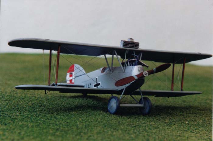
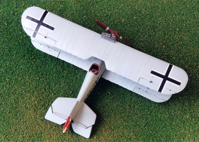 The
aeroplane was painted light grey. Pictures of the aeroplane are inconclusive
with regard to colour, however, the example in the Swedish Air Force Museum
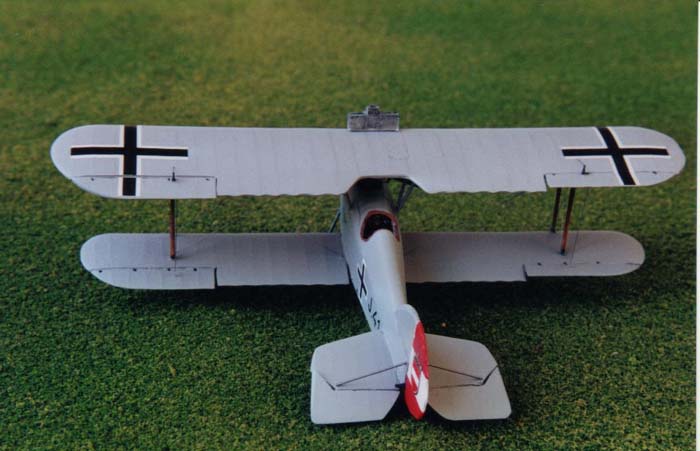
is a light to mid-grey. The vertical tail was then decaled using decal
paper sprayed red and white, and a Crown and Cross decal from Pegasus.
This tail part was then glued to the painted fuselage.
The
aeroplane was painted light grey. Pictures of the aeroplane are inconclusive
with regard to colour, however, the example in the Swedish Air Force Museum
is a light to mid-grey. The vertical tail was then decaled using decal
paper sprayed red and white, and a Crown and Cross decal from Pegasus.
This tail part was then glued to the painted fuselage.
I have heard many sad stories about the effect of temperature on resin parts, especially parts that are required to support the model. Never having built a resin kit, I decided to take this to heart and I did not use any of the resin parts for struts or the landing gear legs. The interplane struts were carved from bamboo. This is a fairly straightforward if somewhat time-consuming exercise. You can purchase a packet of bamboo chopsticks that will give a lifetime's supply of strut material. Chop off a small piece a bit longer and thicker than you need. Take a small flat block of wood and tape a piece of double-sided tape to it. Stick the piece of bamboo you chopped off to the tape and start sanding using 220-grit wet/dry sandpaper. Once it is sanded down a bit and smooth, turn it over and do the other side, shaping and smoothing as you sand. Take the 'strut' off the tape, sand it to the right width, use a knife to shorten it to the right length and taper it. Each strut took me about 20 minutes, though I had to throw out a couple that were not right. When you are done, you have real wooden struts. I stained them with wood stain, and then brushed them with a mix of Future and 'Leather brown'. The cabane struts were scratched from .020" plastic rod and tapered at the ends to make them fit the N-shape configuration. The landing gear struts were made from piano wire.
 I
attached the interplane struts to the upper wing and aligned the struts
appropriately. I then glued the struts and upper wing sub-assembly to
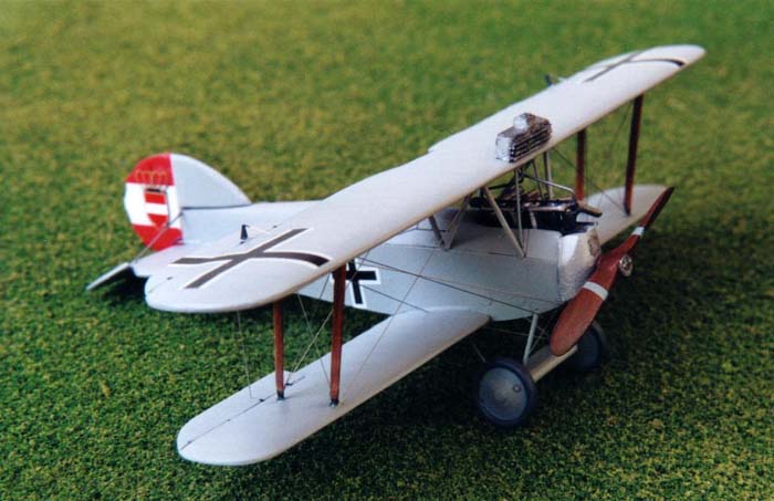
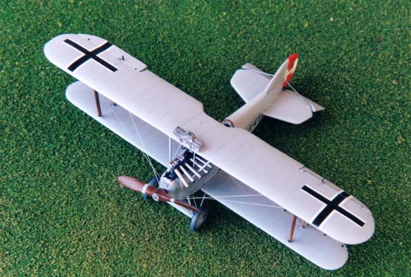
the lower wing. I gave the exhaust unit atop the upper wing a coat of
aluminum paint, followed by a black gouache wash, and then glued it to
the wing.
I
attached the interplane struts to the upper wing and aligned the struts
appropriately. I then glued the struts and upper wing sub-assembly to
the lower wing. I gave the exhaust unit atop the upper wing a coat of
aluminum paint, followed by a black gouache wash, and then glued it to
the wing.
I used some fine piano wire to fashion the exhaust wires from the engine to the top wing. The same material was used for the diagonal struts either side of the horizontal tail. A slightly larger diameter piano wire was used to make the guns inserted either side of the engine.
The J 41 was printed from Microsoft Word onto decal paper using an HP LaserJet IIIp. The black and white cross decals were taken from the spares box, as I attempted to match the size and position of the marking from pictures and profiles in Grosz's book..
Conclusion and Recommendations
 This
is good kit of a less mainstream aeroplane; there are few alternative
kits available. My primary criticism is that the upper wing's fuel tanks
should be molded separately, which would provide the builder with a straightforward
choice of the Swedish or Austro-Hungarian version. As it was, I agonized
and procrastinated for months, deciding which version to build, although
the building process turned out to be enjoyable. A secondary criticism
is that the load bearing parts, such as the struts and landing gear, should
not be made from resin due to this material's reaction to changes in temperature.
The manufacturers have a choice; they could provide struts made of an
alternative material; for example metal, or they could provide a template
for the builder to scratch build these parts. I used the resin struts
and landing gear as templates but this seems an expensive way to provide
a template. Finally, it would be helpful if the kit contained even the
most rudimentary instructions.
This
is good kit of a less mainstream aeroplane; there are few alternative
kits available. My primary criticism is that the upper wing's fuel tanks
should be molded separately, which would provide the builder with a straightforward
choice of the Swedish or Austro-Hungarian version. As it was, I agonized
and procrastinated for months, deciding which version to build, although
the building process turned out to be enjoyable. A secondary criticism
is that the load bearing parts, such as the struts and landing gear, should
not be made from resin due to this material's reaction to changes in temperature.
The manufacturers have a choice; they could provide struts made of an
alternative material; for example metal, or they could provide a template
for the builder to scratch build these parts. I used the resin struts
and landing gear as templates but this seems an expensive way to provide
a template. Finally, it would be helpful if the kit contained even the
most rudimentary instructions.
This was my first resin kit and overall I was highly satisfied. It fits together well, has a fair amount of fine detail and while I would not recommend it for a beginner, it is certainly within the capability of someone who has built two or three biplanes.
Thanks to Lubos Vinar of Hobbyshop.cz (formerly VAMP Mail Order) for the review sample.
Reference
-
Peter M. Grosz, George Haddow and Peter Schiemer, 'Austro-Hungarian Army Aircraft of World War One.' Flying Machine Press, Mountain View, California, 1993.